LiveLink
The following section will show you how to use FEM-Design connection. The connection allows you to dialog with FEM-Design instance on the fly as if you were using the application to perform specific task. The connection links Grasshopper to FEM-Design and, therefore, the methods are applied to the opened model in FEM-Design.
You can download the Grasshopper definition used in this tutorial from here 👉Grasshopper Definition
- It is not possible to modify the model in Grasshopper while the Properties dialog in FEM-Design is open. Please close the properties dialog before making changes in Grasshopper.
Async Mode
The LiveLink component can operate in two modes: Async (asynchronous) and Sync (synchronous).
- Sync mode: The Grasshopper canvas will wait for FEM-Design to complete each operation before continuing. This ensures sequential execution but may cause Grasshopper to appear unresponsive during long-running tasks.
- Async mode: Operations are executed asynchronously, allowing Grasshopper to remain responsive while FEM-Design processes tasks in the background.
You can switch between Async and Sync modes using the FEM-Design menu in the Grasshopper toolbar.
Async mode cannot be used for iterative analysis. If you need to perform iterative workflows (e.g., optimization loops, parameter studies), you must use Sync mode to ensure proper sequential execution of operations.

Connection
Connection opens a specific instance of FEM-Design that will run the methods.

Open model
Open a model on an instance of FEM-Design.

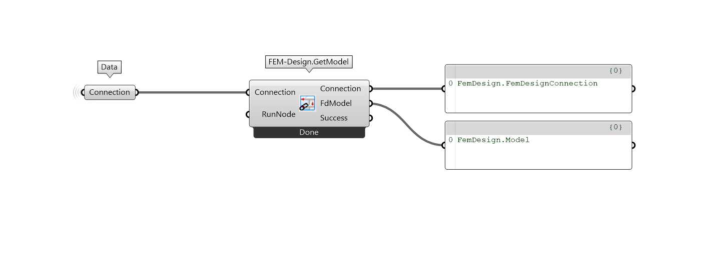
Get model
Get the current opened model from FEM-Design instance.
Calculations
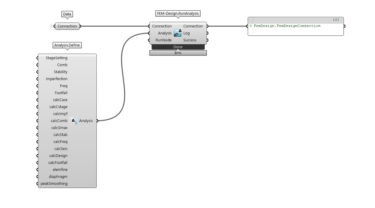
Run analysis
Run design

Results
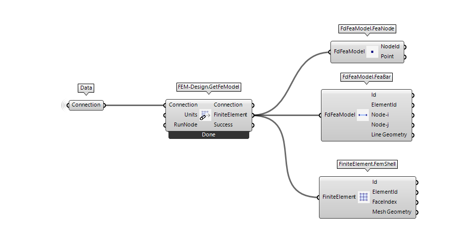
Get FEA model
Get load case and combination results

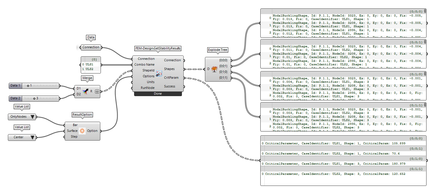
Get stability results

Get quantities

Get results from bsc
While we provide some ready result types to be extract (i.e ResultType), it might be that you want to extract some specific results that they have not been implemented yet. In that scenario, you can use the batch .bsc file which will inform the software to give you back the desired results.
If you want to create the .bsc file, you need to:
- Open
FEM-Design - Click on
Tools - Select
List... (TAB)
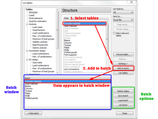
You can now select the results that you want to extract and create the .bsc file that you can use in the Grasshopper component.
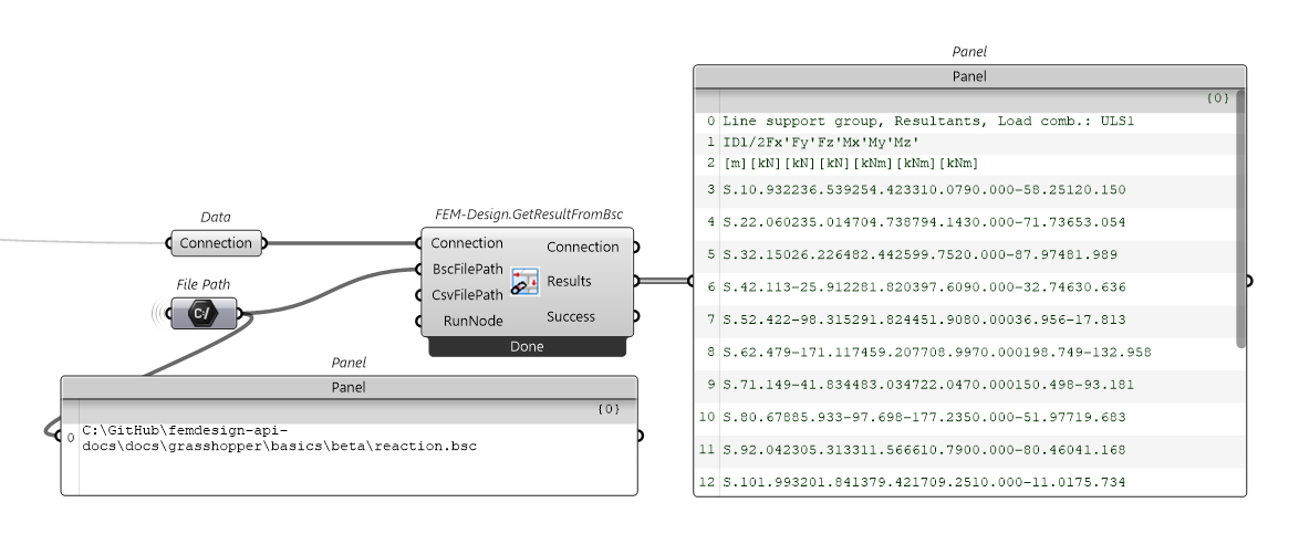
Configurations
Set global configurations
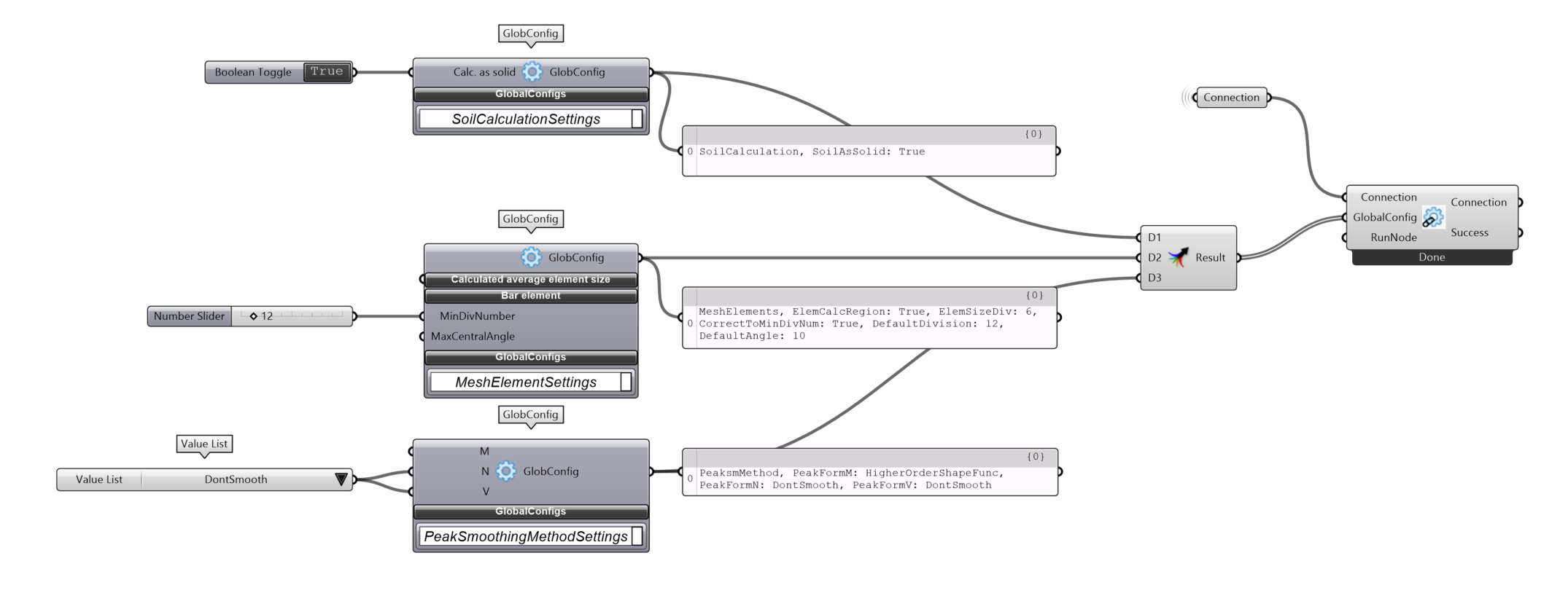
SetGlobalConfigurations defines the calculation settings that will instruct FEM-Design in operation like creating the finite element mesh. The API provides a set of components and a preset file that you can modify to fullfil your need. However, most of the structure can be analysed with the already specified values.
Using specific components

Preset file
The default global configuration file can be accessed from the following path:
%AppData%\McNeel\Rhinoceros\packages\7.0\FemDesign\cmdglobalcfg.xml

To access FEM-Design -> Settings -> Calculation, you need to use a specific XML file that contains the commands to control the global calculation configurations for Soil, Mesh and Peak Smoothing. Below is a fully prepared file with some guidance, called cmdglobalcfg.xml which contains the default settings for the software. The current approach is to modify this text file with the desired values.
cmdglobalcfg.xml
<?xml version="1.0" encoding="UTF-8"?>
<!-- (c) StruSoft 2012-2021, http://www.strusoft.com -->
<cmdglobalcfg command="$ FEM $CODE(GLOBALCFG)">
    <!-- modify the value below if you want to change the Globalcfg setting -->
    <!-- attributes that start with 'f' must be 0 or 1 -->
    <!-- attributes that start with 'r' are double numbers -->
    <!-- attributes that start with 's' are integer numbers -->
    <mesh_general
        fAdjustToLoads = "0" />
    <mesh_elements
        fElemCalcRegion = "1"
        rElemSizeDiv = "6.0"
        fCorrectToMinDivNum = "1"
        sDefaultDivision = "2"
        rDefaultAngle = "15.0" />
    <mesh_functions
        fRefineLocally = "1"
        sRefineMaxStepNum = "5"
        fMaxIterWarning = "0"
        fReduceSize = "1"
        sSmoothStepNum = "3"
        fCheckMeshGeom = "1"
        rCheckGeomMinAngle = "10.0"
        rCheckGeomMaxAngle = "170.0"
        rCheckGeomMaxSideRatio = "8.0"
        fCheckMeshOverlap = "1"
        fCheckMeshTopology = "1" />
    <mesh_prepare
        fAutoRegen = "1"
        fThPeak = "1"
        fThBeam = "0"
        fThColumn = "1"
        fThTruss = "0"
        fThFicBeam = "0"
        fThFreeEdge = "0"
        fThRegionBorder = "0"
        fThSuppPt = "1"
        fThSuppLn = "0"
        fThSuppSf = "0"
        fThEdgeConn = "0"
        fThConnPt = "0"
        fThConnLn = "0"
        fThConnSf = "0"
        fThLoadPt = "0"
        fThLoadLn = "0"
        fThLoadSf = "0"
        fThFixPt = "0"
        fThFixLn = "0"
        fAutoRebuild = "1"
        fAutoSmooth = "1"
        fAutoCheck = "0" />
    <peaksm_method
        sPeakFormFunc_M = "1"
        sPeakFormFunc_N = "1"
        sPeakFormFunc_V = "1" />
    <peaksm_auto
        fPeakBeam = "0"
        fPeakColumn = "1"
        fPeakTruss = "0"
        fPeakFicBeam = "0"
        fPeakPlate = "0"
        fPeakWall = "0"
        fPeakFicShell = "0"
        fPeakSuppPt = "1"
        fPeakSuppLn = "0"
        fPeakSuppSf = "0"
        fPeakConnPt = "0"
        fPeakConnLn = "0"
        fPeakConnSf = "0"
        rPeakFactor = "0.5" />
</cmdglobalcfg>
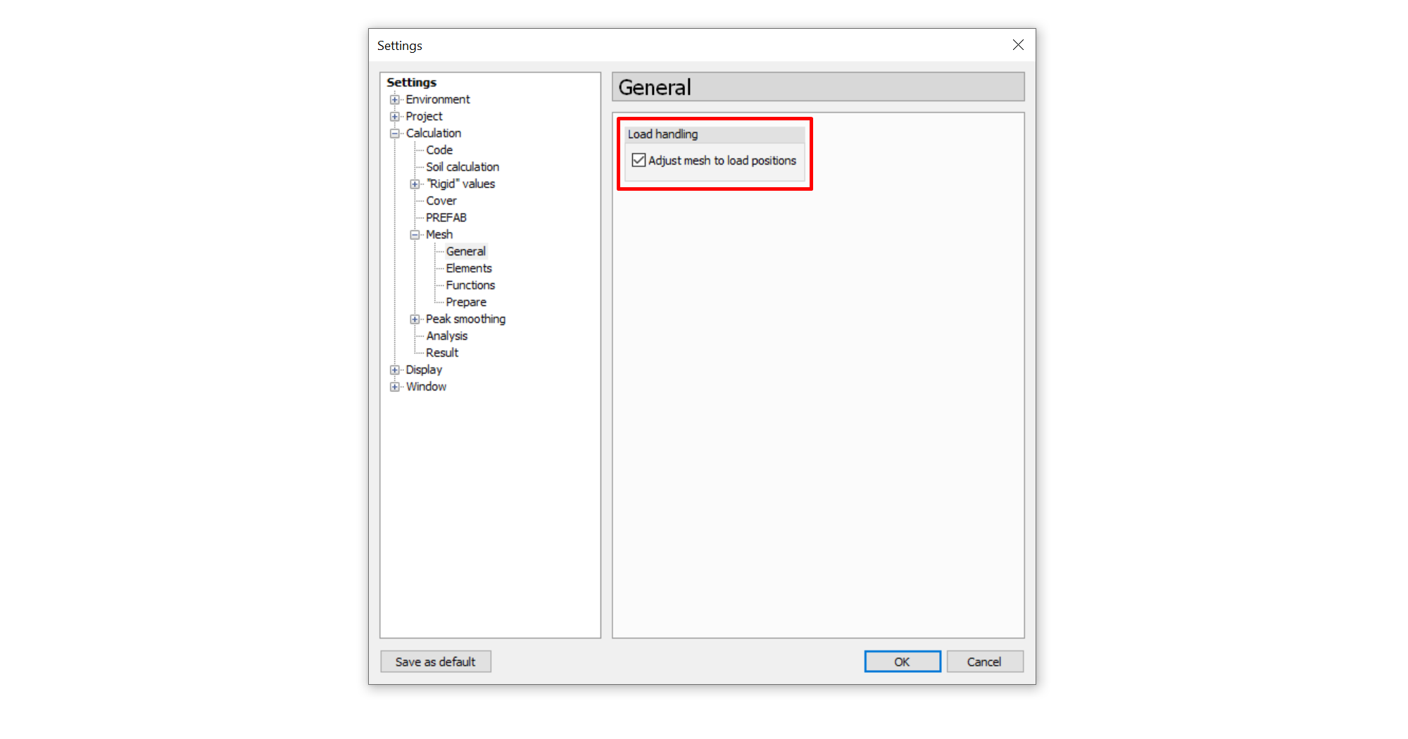
For example, if you want to change the general mesh settings to enable Adjust mesh to load positions, you need to set the fAdjustToLoads attribute to 1 (true).
    <mesh_general
        fAdjustToLoads = "1" />
Or, if you want to change the lowest minimum division number of bar elements to 10, you need to set the sDefaultDivision attribute to 10.
    <mesh_elements
        fElemCalcRegion = "1"
        rElemSizeDiv = "6.0"
        fCorrectToMinDivNum = "1"
        sDefaultDivision = "10"
        rDefaultAngle = "15.0" />
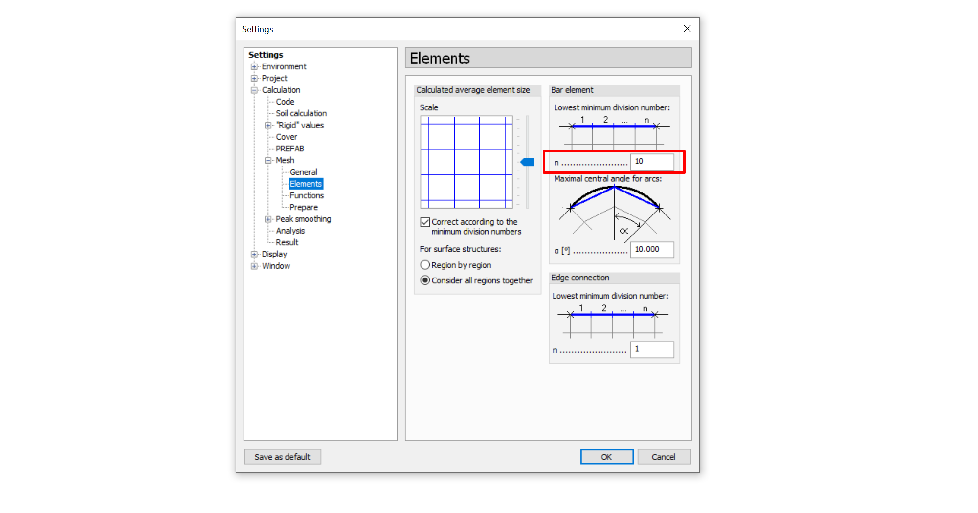
Most of the XML attribute names reflect the functionality of the FEM design settings. The attribute value types are logically the same as when you set them manually in the GUI. For example, the attributes corresponding to checkboxes are Boolean parameters, so their value can be 0 or 1. If you have to specify a number using the GUI, this means that the attribute value will be an integer or a double, depending on the case.
Keep in mind:
- attributes beginning with 'f' must be 0 or 1
- attributes beginning with 'r' are double numbers
- attributes beginning with 's' are integers
Set design configurations
SetDesignConfigurations defines the calculation/design settings that will instruct FEM-Design in setting up the parameters to perform calculation/design check. The API provides a set of components and a preset file that you can modify to fullfil your need.
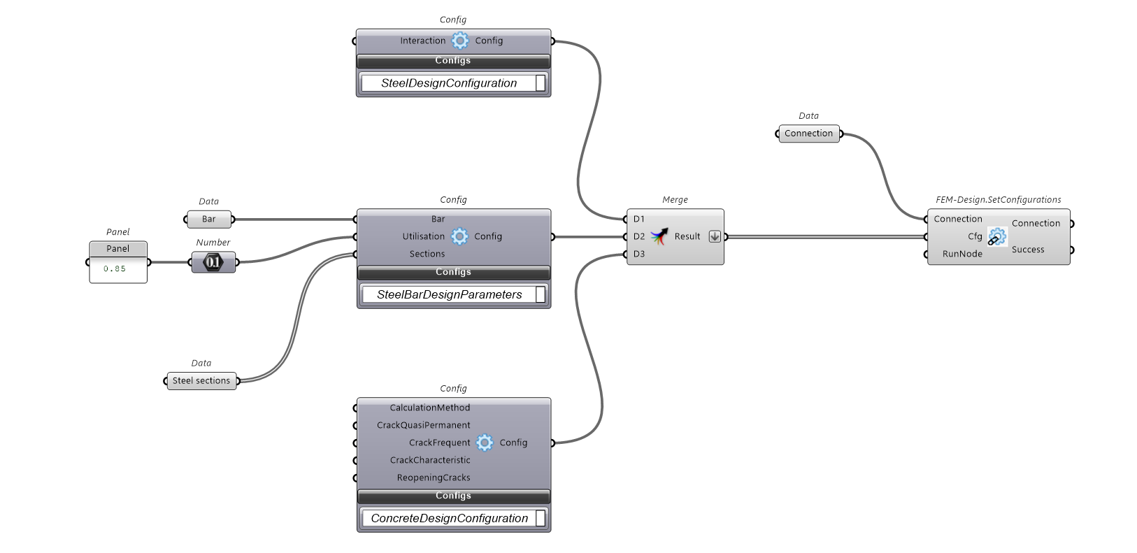
Steel design parameters

Steel design configuration

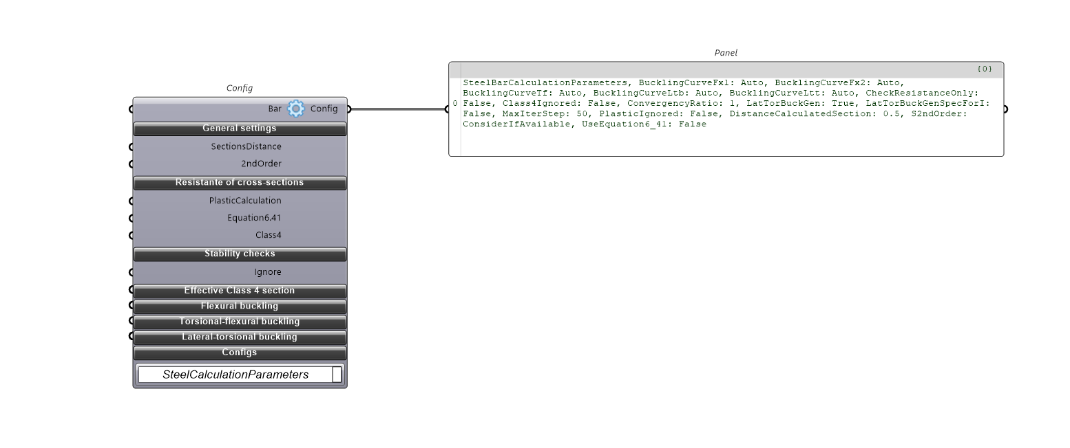
Steel calculation parameters
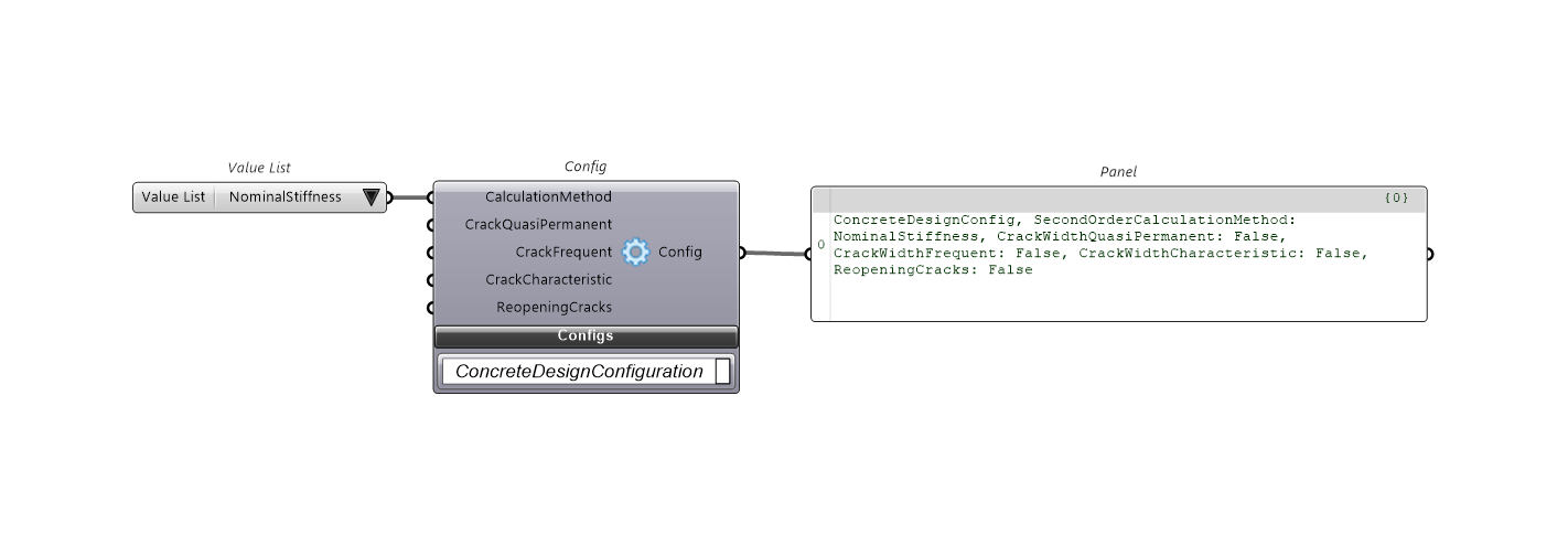
Concrete design configuration
Preset file
SetConfigurations defines the design parameter configurations. Parameters can be set using a preset file located at:
%AppData%\McNeel\Rhinoceros\packages\7.0\FemDesign\cfg.xml
Alternatively, you can use specific components built to customize the settings.

To set up design configurations using a preset file, we have the same solution as for the global configurations. Config input instructs FEM-Design to apply the design parameters to perform structural check and design. The preset file approach involves modifying the cfg.xml file with the desired values.
cfg.xml - all parameters
<?xml version="1.0" encoding="UTF-8"?>
<configs>
    <CONFIG fIgnoreAnnexForShearStrength="false" StripeWidth="1" type="CCMSCONFIG"></CONFIG>
    <CONFIG type="CCCOCONFIG"></CONFIG>

    <!-- EUROCODE FOUNDATION CONFIG -->
    <CONFIG acc_Au_0="1.35" acc_Au_1="1" acc_c_0="1" acc_c_1="1" acc_cu_0="1" acc_cu_1="1" acc_gamma_0="1" acc_gamma_1="1" acc_phi_0="1" acc_phi_1="1" acc_Rh_0="1" acc_Rh_1="1" acc_Rh_2="1" acc_Rv_0="1" acc_Rv_1="1" acc_Rv_2="1" method_0="0" method_1="0" seis_Au_0="1.35" seis_Au_1="1" seis_c_0="1" seis_c_1="1.25" seis_cu_0="1" seis_cu_1="1.4" seis_gamma_0="1" seis_gamma_1="1" seis_phi_0="1" seis_phi_1="1.25" seis_Rh_0="1" seis_Rh_1="1.1" seis_Rh_2="1" seis_Rv_0="1" seis_Rv_1="1.4" seis_Rv_2="1" settlement_fAlpha="true" settlement_fBeta="false" settlement_fDelta_l="true" settlement_fDelta_s="false" settlement_fOmega="true" settlement_fTheta="true" settlement_rAlpha="0.0066666" settlement_rBeta="0.0066666" settlement_rDelta_l="0.0033333" settlement_rDelta_s="0.05" settlement_rOmega="0.0066666" settlement_rTheta="0.0066666" type="ECFNCONFIG" ult_Au_0="1.35" ult_Au_1="1" ult_c_0="1" ult_c_1="1.25" ult_cu_0="1" ult_cu_1="1.4" ult_gamma_0="1" ult_gamma_1="1" ult_phi_0="1" ult_phi_1="1.25" ult_Rh_0="1" ult_Rh_1="1.1" ult_Rh_2="1" ult_Rv_0="1" ult_Rv_1="1.4" ult_Rv_2="1"></CONFIG>

    <!-- EUROCODE STEEL CONFIG -->
    <CONFIG sInteraction="0" type="ECSTCONFIG"></CONFIG>

    <!-- DESIGN PARAMETERS STEEL BAR -->
    <CONFIG LimitUtilization="0.8" type="CCDESPARAMBARST"  vSection_itemcnt="24"></CONFIG>

    <!-- EUROCODE CALCULATION PARAMETERS STEEL BAR -->
    <CONFIG aBucklingCurve_fx1="-1" aBucklingCurve_fx2="-1" aBucklingCurve_ltb="-1" aBucklingCurve_ltt="-1" aBucklingCurve_tf="-1" CheckResistanceOnly="1" class4Ignored="1" convergencyratio="1" fLatTorBuckGen="1" fLatTorBuckGenSpecForI="0" maxIterStep="50" plasticIgnored="0" rStep="0.5" s2ndOrder="1" type="ECCALCPARAMBARST" UseEqation6_41="0"></CONFIG>

    <!-- EUROCODE CONCRETE CONFIG -->
    <CONFIG s2ndOrder="0" type="ECRCCONFIG"></CONFIG>

    <!-- DESIGN PARAMETERS CONCRETE BAR -->
    <CONFIG desparam_fSymmCirc="0" desparam_fSymmY="0" desparam_fSymmZ="0" desparam_hfVibrator="" desparam_hSteel_aux="0" desparam_hSteel_long="0" desparam_hSteel_stir="0" desparam_lProfile_aux="1" desparam_lProfile_long="1" desparam_lProfile_stir="1" desparam_rAggregate="20" desparam_rDiam_aux="8" desparam_rDiam_long_aux="16" desparam_rDiam_stir="8" desparam_vCover_itemcnt="1" desparam_vCover_r_0="20" LimitUtilization="1" type="CCDESPARAMBARRCREAL" vSection_csec_0="2c14a0a2-63c8-4586-a30e-97b20ea376fb" vSection_itemcnt="1"></CONFIG>

    <!-- EUROCODE CALCULATION PARAMETERS CONCRETE BAR -->
    <CONFIG aEcc_Imperfection="0" aEcc_Minimal="0" aEcc_SecondOrder="0" afEcc_Imperfection="TRUE" afEcc_Minimal="TRUE" afEcc_SecondOrder="TRUE" cot_theta="1.25" csf="1" fColumn="FALSE" fCompReinf="0" fEccUdImpf="FALSE" fEccUdMin="FALSE" fIgnoreTorsion="FALSE" firestdRC_dt="5" firestdRC_epsf="1" firestdRC_epsm="0.7" firestdRC_fCheckShearAndTorsion="0" firestdRC_fConsiderInAnchorageLength="0" firestdRC_fDesignForFire="1" firestdRC_lAggregateType="0" firestdRC_lDesignMethod="1" firestdRC_lManufactureType="0" firestdRC_lMeshDivisor="9" firestdRC_lMoistureContent="1" firestdRC_lSteelClass="0" firestdRC_lThermalConductivityLimit="0" firestdRC_Phi="1" firestdRC_rConcDensity="2300" firestdRC_TempCurve="0" firestdRC_treq="120" fMomentforlambdalim="FALSE" rCrackLimit="1" rEccUdImpf0="0" rEccUdImpf1="0" rEccUdMin0="0" rEccUdMin1="0" rStep="0.5" s2ndOrder="1" type="ECCALCPARAMBARRC"></CONFIG>

    <!-- EUROCODE CALCULATION PARAMETERS CONCRETE SHELL -->
    <CONFIG afShellBucklingEccApplied_Imperfection="TRUE" afShellBucklingEccApplied_Minimal="TRUE" afShellBucklingEccApplied_SecondOrder="TRUE" arEccUdAdd0="0" arEccUdAdd1="0" arEccUdMin0="0" arEccUdMin1="0" csf="1" face_0_fXOnTop="0" face_0_hSteel_x="0" face_0_hSteel_y="0" face_0_rCover_x="20" face_0_rCover_y="30" face_0_rCwLimit="0.4" face_0_rDiam_x="10" face_0_rDiam_y="10" face_0_rEcc="0" face_1_fXOnTop="0" face_1_hSteel_x="0" face_1_hSteel_y="0" face_1_rCover_x="20" face_1_rCover_y="30" face_1_rCwLimit="0.4" face_1_rDiam_x="10" face_1_rDiam_y="10" face_1_rEcc="0" fCompressed="0" fDescartes="1" firestdRCShell_dt="5" firestdRCShell_epsf="1" firestdRCShell_epsm="0.7" firestdRCShell_fCheckShellBuckling="0" firestdRCShell_lAggregateType="0" firestdRCShell_lDesignMethod="0" firestdRCShell_lManufactureType="0" firestdRCShell_lMeshDivisor="9" firestdRCShell_lMoistureContent="1" firestdRCShell_lSteelClass="0" firestdRCShell_lThermalConductivityLimit="0" firestdRCShell_Phi="1" firestdRCShell_rConcDensity="2300" firestdRCShell_TempCurve="0" firestdRCShell_treq="120" fMinReinf="1" fSingleLayer="false" lb="1.3385" type="ECCALCPARAMSHELLRC"></CONFIG>

    <!-- EUROCODE CALCULATION PARAMETERS CONCRETE SHELL SHEAR -->
    <CONFIG cot_theta="1" hSteel="0" type="ECCALCPARAMSHELLRCSHEAR"></CONFIG>

    <!-- DESIGN PARAMETERS CONCRETE SHELL -->
    <CONFIG face_0_fBaseNet="TRUE" face_0_fLockSpace="TRUE" face_0_Lay_0_0_hSteel="0" face_0_Lay_0_0_rDiam="10" face_0_Lay_0_0_rMaxSpace="300" face_0_Lay_0_0_rMinSpace="50" face_0_Lay_0_0_rRectBandMin="0" face_0_Lay_0_0_rRectStep="1000" face_0_Lay_0_0_rRound="100" face_0_Lay_0_0_rSpace="150" face_0_Lay_0_0_rSpaceStep="50" face_0_Lay_0_0_sMethod="1" face_0_Lay_0_1_hSteel="0" face_0_Lay_0_1_rDiam="10" face_0_Lay_0_1_rMaxSpace="300" face_0_Lay_0_1_rMinSpace="50" face_0_Lay_0_1_rRectBandMin="0" face_0_Lay_0_1_rRectStep="1000" face_0_Lay_0_1_rRound="100" face_0_Lay_0_1_rSpace="150" face_0_Lay_0_1_rSpaceStep="50" face_0_Lay_0_1_sMethod="1" face_0_Lay_1_0_hSteel="0" face_0_Lay_1_0_rDiam="10" face_0_Lay_1_0_rMaxSpace="300" face_0_Lay_1_0_rMinSpace="50" face_0_Lay_1_0_rRectBandMin="0" face_0_Lay_1_0_rRectStep="1000" face_0_Lay_1_0_rRound="100" face_0_Lay_1_0_rSpace="150" face_0_Lay_1_0_rSpaceStep="50" face_0_Lay_1_0_sMethod="0" face_0_Lay_1_1_hSteel="0" face_0_Lay_1_1_rDiam="10" face_0_Lay_1_1_rMaxSpace="300" face_0_Lay_1_1_rMinSpace="50" face_0_Lay_1_1_rRectBandMin="0" face_0_Lay_1_1_rRectStep="1000" face_0_Lay_1_1_rRound="100" face_0_Lay_1_1_rSpace="150" face_0_Lay_1_1_rSpaceStep="50" face_0_Lay_1_1_sMethod="0" face_0_Lay_2_0_hSteel="0" face_0_Lay_2_0_rDiam="12" face_0_Lay_2_0_rMaxSpace="300" face_0_Lay_2_0_rMinSpace="50" face_0_Lay_2_0_rRectBandMin="0" face_0_Lay_2_0_rRectStep="1000" face_0_Lay_2_0_rRound="100" face_0_Lay_2_0_rSpace="150" face_0_Lay_2_0_rSpaceStep="50" face_0_Lay_2_0_sMethod="1" face_0_Lay_2_1_hSteel="0" face_0_Lay_2_1_rDiam="12" face_0_Lay_2_1_rMaxSpace="300" face_0_Lay_2_1_rMinSpace="50" face_0_Lay_2_1_rRectBandMin="0" face_0_Lay_2_1_rRectStep="1000" face_0_Lay_2_1_rRound="100" face_0_Lay_2_1_rSpace="150" face_0_Lay_2_1_rSpaceStep="50" face_0_Lay_2_1_sMethod="1" face_1_fBaseNet="FALSE" face_1_fLockSpace="TRUE" face_1_Lay_0_0_hSteel="0" face_1_Lay_0_0_rDiam="10" face_1_Lay_0_0_rMaxSpace="300" face_1_Lay_0_0_rMinSpace="50" face_1_Lay_0_0_rRectBandMin="0" face_1_Lay_0_0_rRectStep="1000" face_1_Lay_0_0_rRound="100" face_1_Lay_0_0_rSpace="150" face_1_Lay_0_0_rSpaceStep="50" face_1_Lay_0_0_sMethod="1" face_1_Lay_0_1_hSteel="0" face_1_Lay_0_1_rDiam="10" face_1_Lay_0_1_rMaxSpace="300" face_1_Lay_0_1_rMinSpace="50" face_1_Lay_0_1_rRectBandMin="0" face_1_Lay_0_1_rRectStep="1000" face_1_Lay_0_1_rRound="100" face_1_Lay_0_1_rSpace="150" face_1_Lay_0_1_rSpaceStep="50" face_1_Lay_0_1_sMethod="1" face_1_Lay_1_0_hSteel="0" face_1_Lay_1_0_rDiam="10" face_1_Lay_1_0_rMaxSpace="300" face_1_Lay_1_0_rMinSpace="50" face_1_Lay_1_0_rRectBandMin="0" face_1_Lay_1_0_rRectStep="1000" face_1_Lay_1_0_rRound="100" face_1_Lay_1_0_rSpace="150" face_1_Lay_1_0_rSpaceStep="50" face_1_Lay_1_0_sMethod="0" face_1_Lay_1_1_hSteel="0" face_1_Lay_1_1_rDiam="10" face_1_Lay_1_1_rMaxSpace="300" face_1_Lay_1_1_rMinSpace="50" face_1_Lay_1_1_rRectBandMin="0" face_1_Lay_1_1_rRectStep="1000" face_1_Lay_1_1_rRound="100" face_1_Lay_1_1_rSpace="150" face_1_Lay_1_1_rSpaceStep="50" face_1_Lay_1_1_sMethod="0" face_1_Lay_2_0_hSteel="0" face_1_Lay_2_0_rDiam="12" face_1_Lay_2_0_rMaxSpace="300" face_1_Lay_2_0_rMinSpace="50" face_1_Lay_2_0_rRectBandMin="0" face_1_Lay_2_0_rRectStep="1000" face_1_Lay_2_0_rRound="100" face_1_Lay_2_0_rSpace="150" face_1_Lay_2_0_rSpaceStep="50" face_1_Lay_2_0_sMethod="1" face_1_Lay_2_1_dbDiam_itemcnt="0" face_1_Lay_2_1_hSteel="0" face_1_Lay_2_1_rDiam="12" face_1_Lay_2_1_rMaxSpace="300" face_1_Lay_2_1_rMinSpace="50" face_1_Lay_2_1_rRectBandMin="0" face_1_Lay_2_1_rRectStep="1000" face_1_Lay_2_1_rRound="100" face_1_Lay_2_1_rSpace="150" face_1_Lay_2_1_rSpaceStep="50" face_1_Lay_2_1_sMethod="1" LimitUtilization="1" type="CCDESPARAMSHELLRC"></CONFIG>

    <!-- DESIGN PARAMETERS CONCRETE SHELL SHEAR -->
    <CONFIG dbDiam_DbDiam_0="4" dbDiam_DbDiam_1="6" dbDiam_DbDiam_10="25" dbDiam_DbDiam_11="30" dbDiam_DbDiam_12="32" dbDiam_DbDiam_13="35" dbDiam_DbDiam_14="40" dbDiam_DbDiam_2="8" dbDiam_DbDiam_3="10" dbDiam_DbDiam_4="12" dbDiam_DbDiam_5="14" dbDiam_DbDiam_6="16" dbDiam_DbDiam_7="18" dbDiam_DbDiam_8="20" dbDiam_DbDiam_9="22" dbDiam_itemcnt="15" fUniformDiameter="1" hSteel="0" LimitUtilization="1" rRectBandMin="0" rRectStep="1000" rSpaceX="150" rSpaceY="150" sMethod="1" sSpacingMethod="0" type="CCDESPARAMSHELLRCSHEAR"></CONFIG>

    <!-- CALCULATION PARAMETERS TIMBER PANEL -->
    <CONFIG type="CCCALCPARAMTMPANEL"></CONFIG>

    <!-- DESIGN PARAMETERS TIMBER PANEL -->
    <CONFIG LimitUtilization="1" type="CCDESPARAMPANELTM" types_ent_0="" types_ent_1="" types_ent_10="" types_ent_11="" types_ent_12="" types_ent_13="" types_ent_14="" types_ent_15="" types_ent_16="" types_ent_17="" types_ent_18="" types_ent_19="" types_ent_2="" types_ent_20="" types_ent_3="" types_ent_4="" types_ent_5="" types_ent_6="" types_ent_7="" types_ent_8="" types_ent_9="" types_itemcnt="21"></CONFIG>

    <!-- CALCULATION PARAMETERS CLT PANEL -->
    <CONFIG fCheckShearInteraction="1" fCheckTorsion="1" rPlankWidth="100" type="CCCALCPARAMTMPANELCLT"></CONFIG>

    <!-- CALCULATION PARAMETERS CLT PANEL FIRE-->
    <CONFIG aDelaminationMultiplier_eBottom="2" aDelaminationMultiplier_eTop="2" afConsiderDelamination_eBottom="FALSE" afConsiderDelamination_eTop="FALSE" afFireExposed_eBottom="2" afFireExposed_eTop="2" afStructProtection_eBottom="FALSE" afStructProtection_eTop="FALSE" atchstruct_eBottom="30" atchstruct_eTop="30" beta0="0.65" d0="7" fAutoBeta="TRUE" fAutod0="TRUE" fIgnoreReductionFactors="TRUE" fNeglectThinLayers="FALSE" rLimitThicknessForNeglection="3" treq="40" type="ECCALCPARAMTMPANELCLTFIRE"></CONFIG>

    <!-- DESIGN PARAMETERS CLT PANEL FIRE -->
    <CONFIG LimitUtilization="1" type="CCDESPARAMPANELTMCLT" types_ent_0="" types_ent_1="" types_ent_10="" types_ent_11="" types_ent_12="" types_ent_13="" types_ent_14="" types_ent_15="" types_ent_16="" types_ent_17="" types_ent_18="" types_ent_19="" types_ent_2="" types_ent_20="" types_ent_21="" types_ent_22="" types_ent_23="" types_ent_24="" types_ent_25="" types_ent_26="" types_ent_27="" types_ent_28="" types_ent_29="" types_ent_3="" types_ent_30="" types_ent_31="" types_ent_32="" types_ent_33="" types_ent_34="" types_ent_35="" types_ent_36="" types_ent_37="" types_ent_38="" types_ent_39="" types_ent_4="" types_ent_40="" types_ent_41="" types_ent_42="" types_ent_43="" types_ent_44="" types_ent_45="" types_ent_46="" types_ent_47="" types_ent_48="" types_ent_49="" types_ent_5="" types_ent_50="" types_ent_51="" types_ent_52="" types_ent_53="" types_ent_54="" types_ent_55="" types_ent_6="" types_ent_7="" types_ent_8="" types_ent_9="" types_itemcnt="56"></CONFIG>
    <CONFIG Beta0="0.8" k2="0.7" LimitUtilization="1" tch="10" tf="10" type="ECDESPARAMPANELTMCLTFIRE"></CONFIG>

    <!-- EUROCODE CALCULATION PARAMETERS TIMBER BAR FIRE -->
    <CONFIG fDeflectionCritEssential="0" firestd_dt="5" firestd_epsf="1" firestd_epsm="0.7" firestd_Phi="1" firestd_TempCurve="0" firestd_treq="120" k2="1" ParametricFire_b="1730" ParametricFire_O="0.2" ParametricFire_qtd="300" ParametricFire_tlim="15" SectionExposion="0" type="ECCALCPARAMBARSTFIRE"></CONFIG>

    <!-- EUROCODE DESIGN PARAMETERS TIMBER BAR FIRE -->
    <CONFIG designmode="0" dThick="1" LimitUtilization="1" MaxThick="10" MinThick="1" TempStep="20" type="CCDESPARAMBARSTFIRE"></CONFIG>

    <!-- DESIGN PARAMETERS TIMBER BAR -->
    <CONFIG LimitUtilization="1" type="CCDESPARAMBARTM" vSection_itemcnt="230"></CONFIG>

    <!-- CALCULATION PARAMETERS TIMBER BAR -->
    <CONFIG rStep="0.5" rtLamination="30" s2ndOrder="1" type="CCCALCPARAMBARTM"></CONFIG>

    <!-- EUROCODE CALCULATION PARAMETERS TIMBER BAR FIRE -->
    <CONFIG afStructProtection_eBottom="FALSE" afStructProtection_eLeft="FALSE" afStructProtection_eRight="FALSE" afStructProtection_eTop="FALSE" atchstruct_eBottom="30" atchstruct_eLeft="30" atchstruct_eRight="30" atchstruct_eTop="30" betan="0.85" eta="1" fAutoBeta="TRUE" firebasic_treq="40" type="ECCALCPARAMBARTMFIRE"></CONFIG>

    <!-- DESIGN PARAMETERS TIMBER BAR FIRE -->
    <CONFIG Beta0="0.8" k2="0.7" LimitUtilization="1" tch="10" tf="10" type="ECDESPARAMBARTMFIRE"></CONFIG>

</configs>
The xml file above contains a wide range of design configurations. The comments within it can help you to identify which attributes you need to change to control the design settings.
For example, if you want to disable Steel design configuration -> Use Method 1, you need to set the sInteraction attribute to 1.
    <!-- EUROCODE STEEL CONFIG -->
    <CONFIG sInteraction="1" type="ECSTCONFIG"></CONFIG>
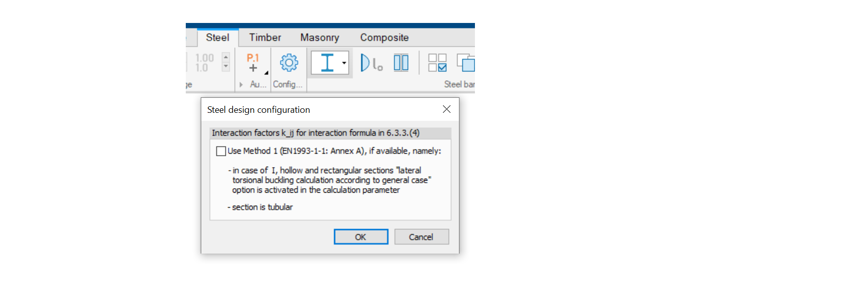
Or, if you want to limit steel utilization to 95%, you need to set the LimitUtilization attribute to 95%.
    <!-- DESIGN PARAMETERS STEEL BAR -->
    <CONFIG LimitUtilization="0.95" type="CCDESPARAMBARST"  vSection_itemcnt="24"></CONFIG>
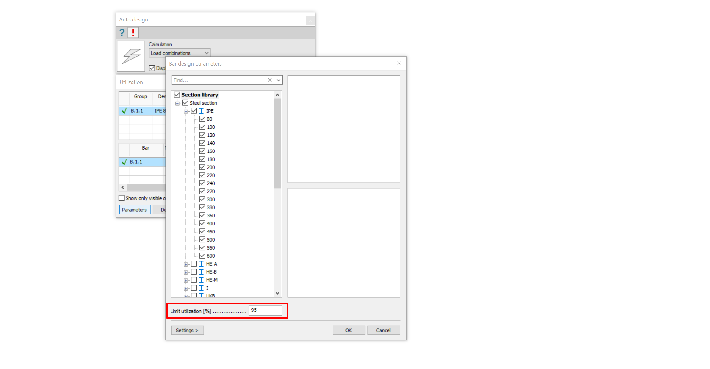
If you are only interested in Steel bar, you can just use the steel design parameters and omit the others.
cfg.xml - steel parameters
<?xml version="1.0" encoding="UTF-8"?>
<configs>
    <CONFIG fIgnoreAnnexForShearStrength="false" StripeWidth="1" type="CCMSCONFIG"></CONFIG>
    <CONFIG type="CCCOCONFIG"></CONFIG>

    <!-- EUROCODE STEEL CONFIG -->
    <CONFIG sInteraction="0" type="ECSTCONFIG"></CONFIG>

    <!-- DESIGN PARAMETERS STEEL BAR -->
    <CONFIG LimitUtilization="0.8" type="CCDESPARAMBARST"  vSection_itemcnt="24"></CONFIG>

    <!-- EUROCODE CALCULATION PARAMETERS STEEL BAR -->
    <CONFIG aBucklingCurve_fx1="-1" aBucklingCurve_fx2="-1" aBucklingCurve_ltb="-1" aBucklingCurve_ltt="-1" aBucklingCurve_tf="-1" CheckResistanceOnly="1" class4Ignored="1" convergencyratio="1" fLatTorBuckGen="1" fLatTorBuckGenSpecForI="0" maxIterStep="50" plasticIgnored="0" rStep="0.5" s2ndOrder="1" type="ECCALCPARAMBARST" UseEqation6_41="0"></CONFIG>
</configs>