Simple beam

The following guide will show you how to create and read results for a simply supported beam.
You can download the Grasshopper definition used in this example from here 👉Grasshopper Definition
On every Grasshopper Component a "baloon" is describing the Grasshopper Component Name. If you want to follow the example along, Double-click on the Grasshopper Canvas and type the name as shown in the pictures.

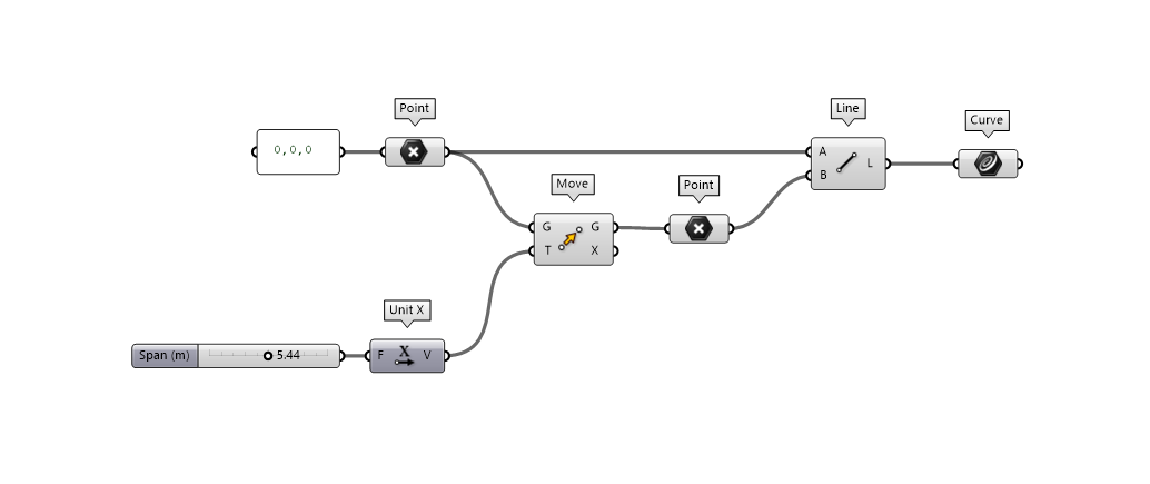
Geometry
The geometry is defined by creating a line between two points using a slider to define a span parameter. Move the slider to left and right to see a change in length of the beam.
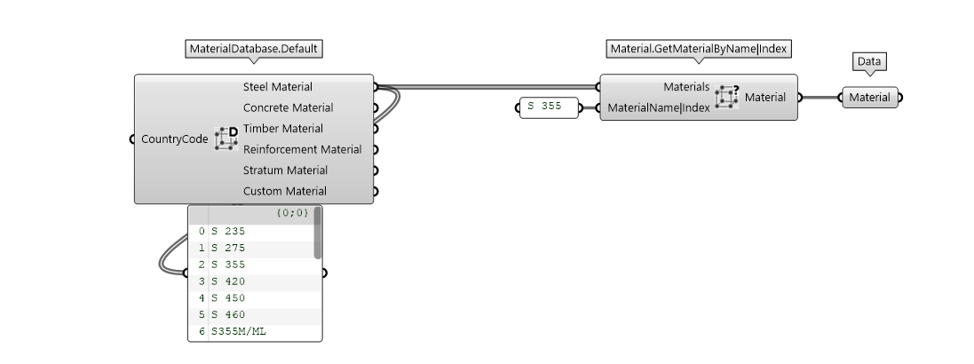
Material
FEM-Design user interface has a database of materials. The MaterialDatabase.Default components returns these materials grouped by type.
The material can be selected using the provided Material.GetMaterialByName|Index. The material name can be seen directly from the output parameter. You can select materials by name or index in the passed list.
Section
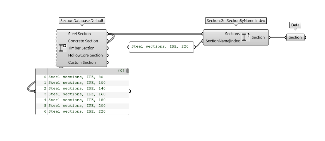
The same workflow is used to select a section. SectionDatabase.Default component returns the FEM-Design sections grouped by type. You can use Section.GetSectionByName|Index to specify your section selection by name or index.
Bar
Bar.Beam is the component necessary to create a Beam element. As you can see from the picture, material and section are plugged in the Bar.Beam component in their respective input parameter. Additionally, you can see a Connectivity component which define the release of the element. By default, the connectivity is defined as Connectiviy.Rigid.

Support
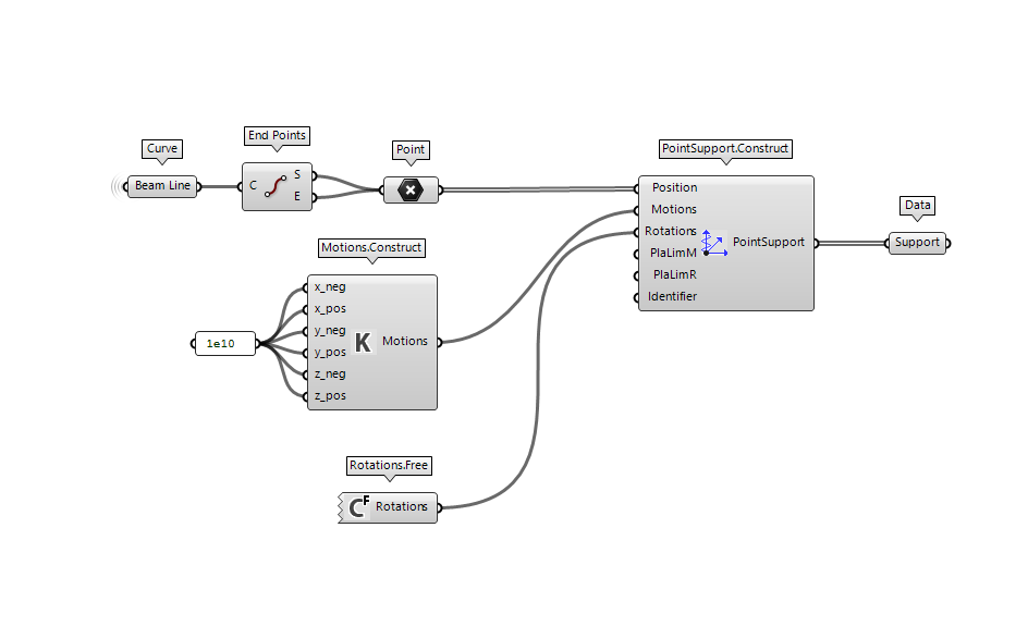
Every structure needs to be anchored to gain stability. FEM-Design API provides you different ways to define the PointSupport some of which are predefined.
The example shows the most flexible way to define the constrained axis and their rigidity. A value equal to 1e+10 assume the support to be rigid in the defined degree of freedom.
Load case
Loads have different intensity, different nature, different probability and different risk.
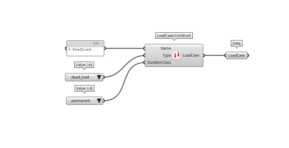
The nature of the load can be translated with the concept of LoadCase.
Load combination
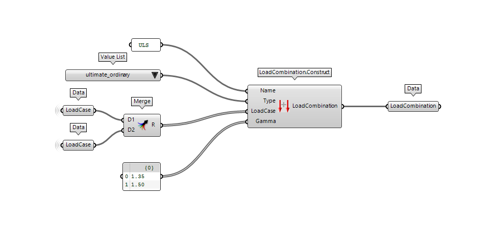
The LoadCombination defines which LoadCases should act simultaneously and their respective Factor.
Load definition
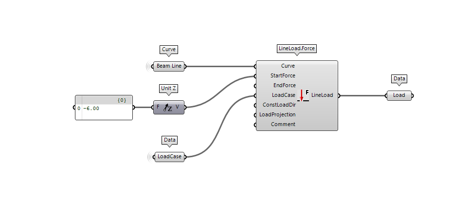
In the following section, you can see how to apply a LineLoad.Force using a Curve to define the distribution of the line load and a Vector to define the intensity and direction.
Assemble
As soon as you have all the ingredients, it is time to combine them all together and Construct your FEM-Design model.
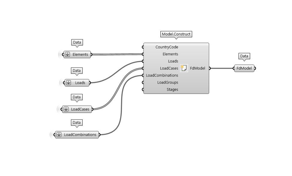
Remember to flatten any input parameters if you want to make sure to create only one model.
Run analysis
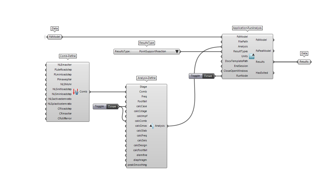
Now that you have a model you can run an analysis using the Application.RunAnalysis component. This component will send your model to the FEM-Design application and run the calculation specified.
Several analysis can be performed through the API but, in this case, we are only interested in the LoadCase and LoadCombination calculation.
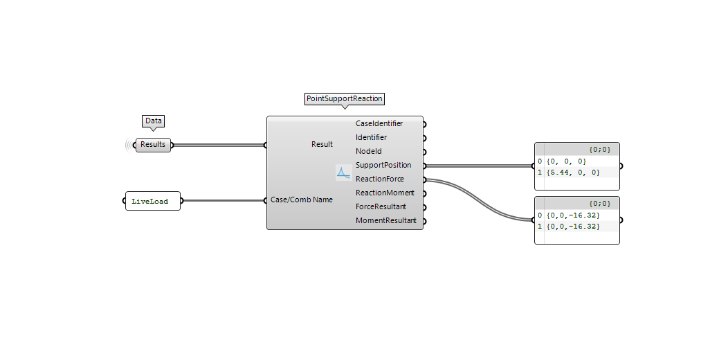
Read results
As the analysis is finished there should be a result output in theApplication.RunAnalysis component Using the ResultType component you can extract and read the results.