21 posts tagged with "API"

View All Tags

Gyroid

Β· One min read
Marco Pellegrino
Nerd Structural Engineer

grasshopper

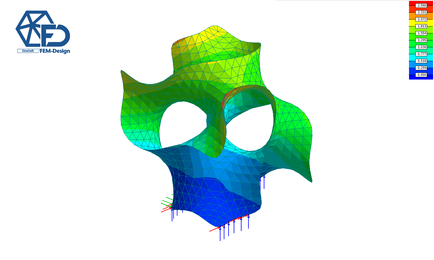
The father of modern triply periodic minimal surfaces (TPMS) passed away.

In the 70s, AlanSchoen was working at NASA and was always queationed about the amount of time he was spending playing with soap and water. He lived to see his work expanding in every direction possible.

You can download the Grasshopper definition used in this tutorial from here πŸ‘‰Grasshopper Definition

πŸ“ Download FEM-Design API
πŸ“ Download StruSoft Trial Version
πŸ“° Newsletter
πŸ™‹ Help

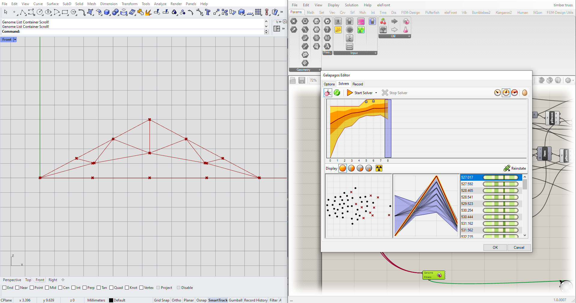
Master thesis - AFRY

Β· One min read
Marco Pellegrino
Nerd Structural Engineer

Master thesis in collaboration with AFRY​

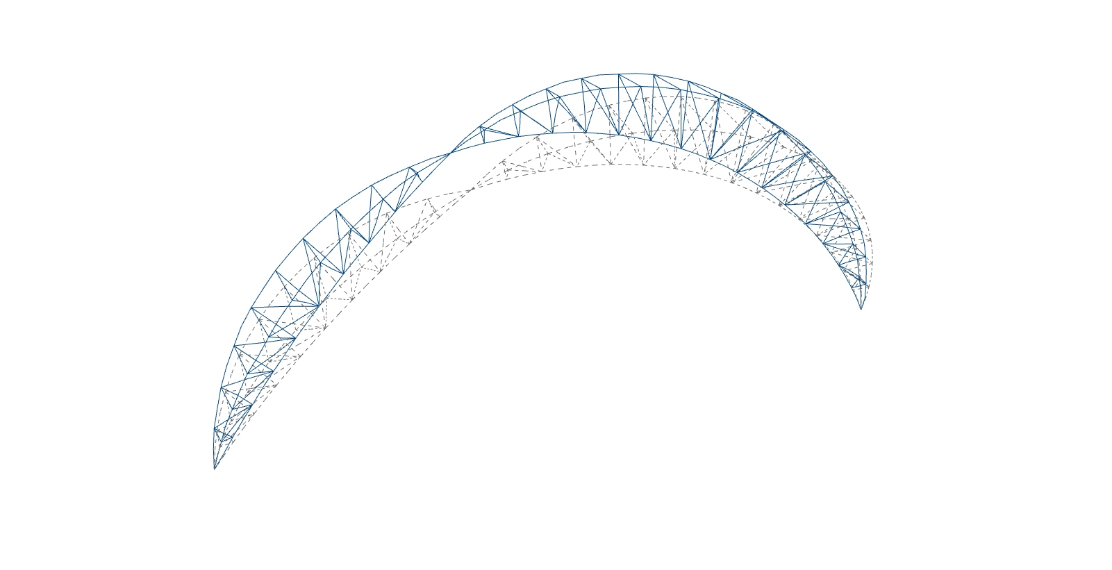
In this blog post, we'll explore the master's thesis collaboration of Olle Carlsson and Fredrik SvΓ€rdstrΓΆm, two students passionate about parametric design. Partnering with AFRY Engineering Company, they embarked on a project centered around creating a truss using Grasshopper, FEM-Design API and Tekla.

Workflow​

  • Grasshopper: Using the visual programming language plugin for Rhino, Olle and Fredrik created a parametric truss structure and manipulated parameters with ease.

  • FEM-Design API: They employed this API to simulate and analyze their truss design's structural performance, ensuring stability and safety.

  • Tekla: By utilizing Tekla, the students transformed their digital truss model into a fabrication-ready version with precise measurements and specifications.

Conclusion​

Olle Carlsson and Fredrik SvΓ€rdstrΓΆm's thesis project exemplifies the potential of parametric design in architecture and engineering. Through their collaboration with AFry Engineering Company, they have opened up new possibilities for the future of design and construction.

Watch the video πŸ‘‡

Watch the video

πŸ“ Download FEM-Design API
πŸ“ Download StruSoft Trial Version
πŸ™‹ Help

Wind on pipe section

Β· One min read
Marco Pellegrino
Nerd Structural Engineer

grasshopper

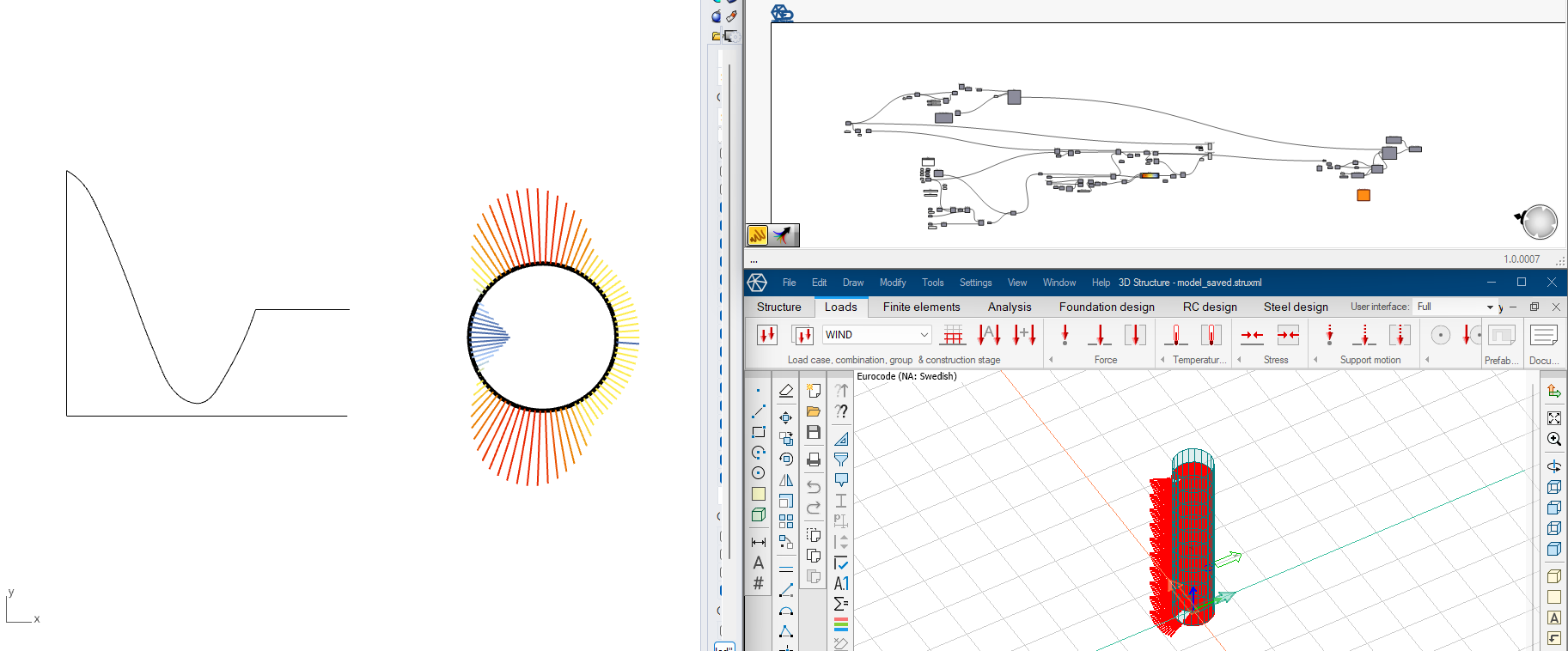
Embracing the Power of Wind Load Analysis with #FEM_Design_API! πŸŒ¬οΈπŸ’πŸ”

While discussing with my colleague Shaho Ruhani about the potential of the API, he told me that it would be great to showcase how we can leverage our tool to perform such a tedious task. πŸ’‘πŸ™Œ

It did not take much time at all and the outcome is amazing! (most of the time was spent in moving through the EC) ⏱️πŸ’ͺ🌟

Do you want to learn more? Do you want to achieve better results in less time? πŸ“šβ°βœ¨ Keep in touch! πŸ“©πŸ€

You can download the Grasshopper definition used in this tutorial from here πŸ‘‰Grasshopper Definition

πŸ“ Download FEM-Design API
πŸ“ Download StruSoft Trial Version
πŸ“° Newsletter
πŸ™‹ Help

Dev meeting 22.5.0

Β· One min read
Marco Pellegrino
Nerd Structural Engineer

grasshopper

We hope you all had a great time at our webinar where we unveiled the latest features of our fantastic development software. It was such an exciting session, and we couldn't be more grateful for your active participation and insightful questions. Now, we're sharing with you all the valuable material from the webinar!

Download the Grasshopper definitions used in the meeting from here πŸ‘‰Grasshopper Definition
Download the pdf presentation used in the meeting from here πŸ‘‰pdf presentation

Below, you can find a quick preview of what it has been discuss.

grasshopper grasshopper grasshopper grasshopper grasshopper grasshopper

πŸ“ Download FEM-Design API
πŸ“ Download StruSoft Trial Version
πŸ™‹ Help

Roller coaster

Β· One min read
Marco Pellegrino
Nerd Structural Engineer

grasshopper

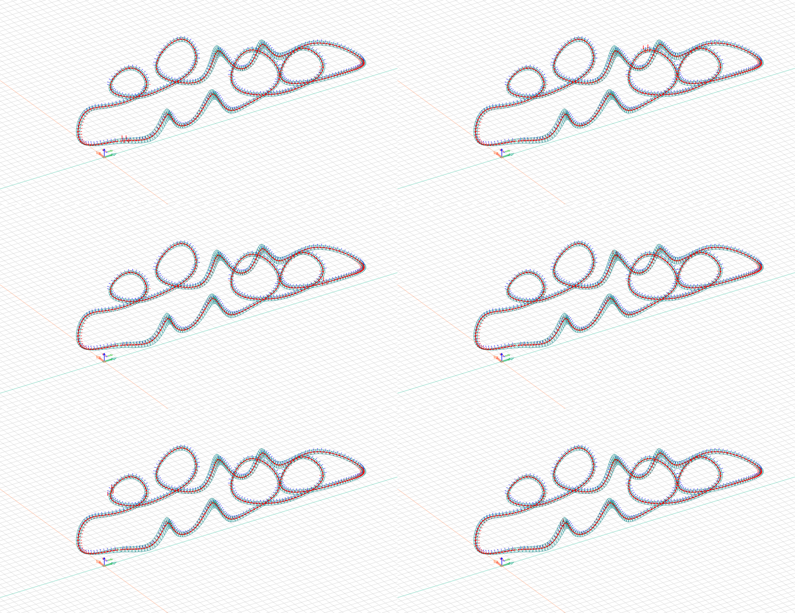
Excited to share my latest development for FEM Design API! πŸŒ‰πŸ’»

As a structural engineer, I have always been fascinated in analyzing a bridge's response to traffict loads.

This powerful components allowed us to quickly specify several scenarios and simulate forces, optimize the design, and ensure safety.

Creating a moving loads have never been so easy! πŸš—πŸš—πŸš—

The feature will be available at the end of the week! Subscribe to our news-letter if you want to stay up-to-date.

You can download the Grasshopper definition used in this tutorial from here πŸ‘‰Grasshopper Definition

πŸ“ Download FEM-Design API
πŸ“ Download StruSoft Trial Version
πŸ™‹ Help

Stability analysis

Β· One min read
Marco Pellegrino
Nerd Structural Engineer

grasshopper

Truss geometry script by Jon Mirtschin

You can download the Grasshopper definition used in this tutorial from here πŸ‘‰Grasshopper Definition

grasshopper

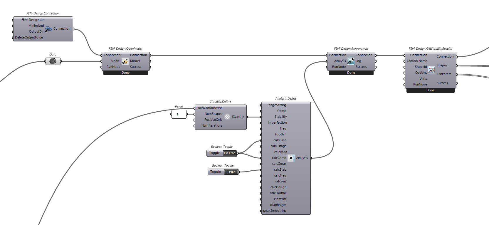
Grasshopper workflow

Slender structures, like columns and towers, are characterized by their elongated shape and high length-to-width ratio. However, stability is a critical concern for these structures. Buckling, a sudden collapse under compressive forces, poses a significant risk. ⚠️

Addressing stability in slender structures is crucial for safety and integrity. By employing design measures and thorough analysis, engineers create structures that can withstand loads and maintain stability over their lifespan. πŸ—οΈ

From 22.5.0, FEM-Design API gives you access to the stability analysis calculation which it will allows you to identify critical issues on your structure.

grasshopper

Buckling results

femdesign_api

FEM-Design API model

πŸ“ Download FEM-Design API
πŸ“ Download StruSoft Trial Version
πŸ™‹ Help

Design group

Β· One min read
Marco Pellegrino
Nerd Structural Engineer

grasshopper

We are definitely living in the era of artificial intelligence and the data are becoming crucial for the training process. πŸ€–πŸ“Š

FEM-Design API can give you access to those! 😊

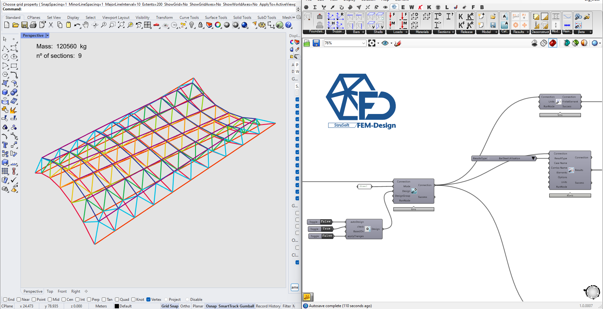
As a matter of fact, we have just given access to the design group that allows you to assign the same section to a group of elements (it is an optimization process) πŸ’‘πŸ”§

If you use Computational Engineering to only import/export the model, I would suggest you to keep track on what it is happening with our product as we have the aim to give you the right tool to perform the best design! πŸ‘©β€πŸ’»πŸ“βœ¨

You can download the Grasshopper definition used in this tutorial from here πŸ‘‰Grasshopper Definition

πŸ“ Download FEM-Design API
πŸ“ Download StruSoft Trial Version
πŸ™‹ Help

Interaction surface

Β· 3 min read
Isak BjΓΆrhag
Business Development Manager
Marco Pellegrino
Nerd Structural Engineer

femdesign

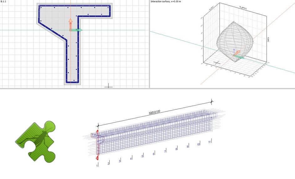
When using an API for parametric design, generative design, or optimization, one crucial aspect is the response speed. At StruSoft, we are dedicated to making the API fast and user-friendly. In line with this commitment, we are introducing a new component for interaction volumes. This component accepts arbitrary section shapes with arbitrarily placed reinforcement and generates the corresponding interaction surface. This is done without running any analysis inside the software which will speed up the process considerably.

What is an interaction surface?​

An interaction volume is a graphical representation that depicts the capacity of a cross-section. It illustrates the permissible combinations of moments and axial force that a concrete section can withstand without failure. In this case, the interaction volume represents a combination of moment around the y-axis, moment around the z-axis, and normal force, essentially forming a volume. Any combination of these forces that falls within the interaction volume is considered acceptable, while those outside of it result in failure.

Please note that the interaction volume only considers the combined effect of moment and normal force and does not include a comprehensive check for shear, buckling, fire design, or other serviceability limit state (SLS) checks.

A compressive normal force in the concrete section generally enhances its moment capacity. By using an interaction volume, you can observe various situations to ensure that the moment capacity is not compromised if the normal force diminishes or decreases.

How could you use this?​

To illustrate the loading, create a point where the x-coordinate corresponds to My, the y-coordinate corresponds to Mz, and the z-coordinate represents the normal force. Utilize the native Grasshopper component 'Mesh Inclusion (MInc)' to determine whether the point is inside the mesh or not.

There are numerous scenarios where this approach can be valuable. Here are a few examples to inspire your imagination:

  • Check all concrete members in the model with the normal force set to zero:

Typically, the lowest moment capacity occurs when the normal force is zero or in tension. Creating a representative load combination under such conditions can be challenging. Instead, you can read the results for all objects into Grasshopper, set all positive normal forces to zero, and use the 'Mesh Inclusion' component to perform the check.

  • Quick preliminary concrete sections:

The interaction volume provides rapid results without requiring any analysis. Hence, it is highly efficient for preliminary section design during the early stages of a project. Once the preliminary design is complete, you can construct the full model and load it into FEM-Design to conduct additional checks, consider serviceability limit states (SLS), and perform fire design.

  • Optimize reinforcement placement in complex section shapes:

Explore various reinforcement placements to optimize the shape of the interaction volume for your specific loading conditions. This approach allows for quick adjustments and fast evaluation of results.

  • Parametric section optimization

By parametrizing your section, you can optimize the cross-section shape to minimize material usage, reduce environmental footprint, or meet other desired criteria.

grasshopper

Grasshopper workflow

You can download the Grasshopper definition used in this tutorial from here πŸ‘‰Grasshopper Definition

You can find our open-source Grasshopper toolbox on food4rhino or in the package manager for Rhino.

Please feel free to contact us if you have any questions or need support!

πŸ“ Download FEM-Design API
πŸ“ Download StruSoft Trial Version
πŸ™‹ Help

FEM-Design section/material with the API

Β· 5 min read
Marco Pellegrino
Nerd Structural Engineer

The following article will show you how to use your personal library of sections and materials with the API.

You can download the Grasshopper definition used in this tutorial from here πŸ‘‰Grasshopper Definition

Dump sections and materials​

FEM-Design stores the section and material data in a binary format which can not be directly read, this means that we need to export the data from FEM-Design using the graphical user interface (GUI).

note

You only need to perform the following procedure once, or when you update your material and section libraries.

The first step is to save your assets in a .struxml file format. In order to do so, in FEM-Design, open the dialog to create a Bar and navigate to Section

Click on export and make sure to select .struxml file format:

Save Sections

Save Sections

Now navigate to Material and perform the same procedure:

Save Materials

Save Materials

Your materials and sections have now been serialised to a .struxml file and they will look something similar to this:

section.struxml
<?xml version="1.0" encoding="UTF-8"?>
<!-- (c) StruSoft 2012-2021, http://www.strusoft.com -->
<database struxml_version="01.00.000" source_software="FEM-Design 21.00.005" start_time="1970-01-01T00:00:00.000" end_time="1970-01-01T00:00:00.000" guid="8b367fc0-4425-48f7-bfa2-2bafca0cd7c8" convertid="00000000-0000-0000-0000-000000000000" standard="EC" country="S" xmlns="urn:strusoft">
<sections>
<section guid="4987c406-68d0-42d5-a158-6ab8f608c851" last_change="1970-01-01T00:00:00.000" action="added" name="Concrete sections, Rectangle, 120x150" type="custom" fd-mat="3" fd_name_code="Concrete sections" fd_name_type="Rectangle" fd_name_size="120x150">
<region_group>
<region>
<contour>
<edge type="line">
<point x="-0.06" y="-0.075" z="0"></point>
<point x="0.06" y="-0.075" z="0"></point>
<normal x="0" y="1" z="0"></normal>
</edge>
<edge type="line">
<point x="0.06" y="-0.075" z="0"></point>
<point x="0.06" y="0.075" z="0"></point>
<normal x="-1" y="0" z="0"></normal>
</edge>
<edge type="line">
<point x="0.06" y="0.075" z="0"></point>
<point x="-0.06" y="0.075" z="0"></point>
<normal x="0" y="-1" z="0"></normal>
</edge>
<edge type="line">
<point x="-0.06" y="0.075" z="0"></point>
<point x="-0.06" y="-0.075" z="0"></point>
<normal x="1" y="0" z="0"></normal>
</edge>
</contour>
</region>
</region_group>
<end></end>
</section>
</sections>
<end></end>
</database>
material.struxml
<?xml version="1.0" encoding="UTF-8"?>
<!-- (c) StruSoft 2012-2021, http://www.strusoft.com -->
<database struxml_version="01.00.000" source_software="FEM-Design 21.00.005" start_time="1970-01-01T00:00:00.000" end_time="2022-10-21T11:03:16.000" guid="01615fbb-a4af-4b7b-96a2-768dae4cd79b" convertid="00000000-0000-0000-0000-000000000000" standard="EC" country="S" xmlns="urn:strusoft">
<materials>
<material guid="6fa49e6a-7088-4054-92f4-da62c762ec4f" last_change="2020-11-11T14:10:49.000" action="added" standard="EC" country="S" name="LΓ€ttklinkerbetong 5.0 M0.5">
<masonry fk="1.2" nu="0.25" rho="0.8" alpha_thermal="0.000012" gammaM_0="2" gammaM_1="1.5" fm="5" K="0.55" alpha="0.7" beta="0.3" elasticity_modulus="1200" creep_U="1.5" creep_Sq="1.5" creep_Sf="1.5" creep_Sc="1.5" phi="1.5" filled_vertical_joints="false" km="0.07" muk="1" ct="0.5" fvk0="0.2" fvlt="0.3"></masonry>
</material>
<material guid="8d399552-5c0f-48ed-9cae-fbfe5b5e2838" last_change="2022-10-21T11:03:16.000" action="added" standard="general" country="n/a" name="MyMaterial">
<custom mass="0.0000000001" E_0="210000000000000" E_1="0" E_2="0" nu_0="0.3" nu_1="0" nu_2="0" alfa_0="0.000012" alfa_1="0" alfa_2="0" G_0="0" G_1="0" G_2="0"></custom>
</material>
</materials>
<end></end>
</database>

Read sections and materials​

FEM-Design API Toolbox for Grasshopper provide a specific component to read and deserialise the .struxml files for sections and materials.

Use SectionDatabase.FromStruxml and MaterialDatabase.FromStruxml to get the deserialise the .struxml files into to objects.

Read Sections

Section from struxml

Read Material

Material from struxml

As soon as you have deserialised the files, you will be able to select your section and material from the list and use it in your project with the API.

Workflow

Element with Custom Section and Custom Material

Create a section database​

There are special case studies where you needs to use custom made sections that are not available in the default database. In such a scenario, you can create your sections with the FEM-Design GUI or the API.

You can define the section geometry as a surface and use it in your workflow. FEM-Design will calculate the mechanical properties automatically and transform the object to a structural section.

gh-Workflow

result

Beam Element with Custom Section in FEM-Design

Save the sections to database​

If you want to import your new sections to FEM-Design this can be done. Save the section objects to a .struxml file with SectionDatabase.Save component and import it in FEM-Design.

result

Save Custom Section to Database

Create family section​

advanced

The parametric environment allows you to define a vast amount of sections with the use of a parametric model.

The example below shows how you can create a family of cellular beam sections that can be used in FEM-Design to perform some optimisation.

You can download the Grasshopper definition used to create a section family from here πŸ‘‰Grasshopper Definition

Progress in construction and production methods makes it possible to refine our design using custom made sections. But how do we "feed" the model with the section family to choose from? One possible solution is to create a logic that build the section geometry as it is shown in the picture below.

family

Section parametrically defined

As soon as you have created the computational logic to create the sections, export them as explained in the previous paragraph and import them in FEM-Design.

family-femdesign

Family in FEM-Design

Every section has a different mechanical properties and FEM-Design will be able to pick the most efficient one when you run the auto-design.

Do you want to learn more about this topic? Get in touch with us.

We are always ready to reply to help you with your issues if you reach out to us! πŸ™‚

πŸ”— Repository

πŸ”—Β Support

πŸ”—Β FEM-Design wiki

Parametric truss

Β· 7 min read
Marco Pellegrino
Nerd Structural Engineer

Hi Everyone πŸ‘‹!

Today, we would like to to show you one simple exercise to get familiar with FEM-Design API through Grasshopper.

The β€œHello World!” for parametric structural engineering. The Parametric Truss!

Untitled

Challenge​

Can you guess which nodes have I constrained?

If you give me the right response, I’ll create a custom example based on your request

Introduction​

The article will highlight the most basic workflow necessary in order to create, analyse and read the results of a generic model.

The workflow consists in the definition of:

  • Geometry
  • Materials
  • Sections
  • Element such Bar, Supports
  • Load
  • Analysis
  • Result Reader

The picture below shows the entire workflow.

Grasshopper script

Grasshopper Script

Geometry definition​

The following script allows you to create a truss with diagonals.

The following parameters can be modified:

  • Length
  • Height
  • Number of Subdivision

Geometry Script

Geometry Script

Truss Geometry Visualisation

Truss Geometry Visualisation

Modifying the parameters will generate a different geometry and therefore, it will be possible to understand their behaviours with the use of a single script. 😎

Pre-processing

The geometries (points, lines and meshes) need to be converted in mechanical elements and in order to do so, the objects require some additional information including:

  • material
  • section
  • connectivity

Material definition​

FEM-Design provide a list of material to choose from. MaterialDatabase.Default component will return some list grouped by material type.

The material can be selected using the provided Material.GetMaterialByName|Index. The material name can be seen directly from the output. It is up to you to decide if you want to use a string or int to select the desired material.

Material Definition Workflow

Material Definition Workflow

Section definition​

The same workflow has been created to select a Section. SectionDatabase.Default component will return some list grouped by section type and Section.GetSectionByName|Index will help you in selecting the right section.

Section Definition Workflow

Section Definition Workflow

Great! πŸŽ‰

We have the minimum ingredients to convert a Line to a Bar.

Element definition​

Bar.Beam is the component necessary to create a Beam element. As you can see from the picture, material and section are plugged in the Bar.Beam component in their respective input. Additionally, you can see a Connectivity component which define the internal release of the element. By default, the connectivity is defined as Connectiviy.Rigid. For our example, Connectiviy.Hinged has been choosen.

Bar.Beam Definition Workflow

Bar.Beam Definition Workflow

Constraint definition​

Every structure needs to be anchored to gain stability. FEM-Design API provides you different way to define the PointSupport and some of them are ready to be use.

Support Constructors

Support Constructors

I personally like to define my anchors with PointSupport.Simple. It is the quickest way to define a generic support if you don’t require to check the uplift.

PointSupport.Simple Definition Workflow

PointSupport.Simple Definition Workflow

Loads​


While I was a student, a teacher of mine use to told me: β€œGravity Load never sleep” πŸ’€

So let’s make sure to apply all the necessary loads!

PS: The article will show you only few type of loads. Make sure to check the load section and see what it is possible.

Load case definition​

Loads have different intensity, different nature, different probability and different risk.

The nature of the load can be translate with the idea of LoadCase .

There are several way to create those and I wanted to show you two. The first option is to use a different component for every load case while the other option (more elegant) is to create a tabular data (it can be a a .csv file or plain text) from which we can read the values.

LoadCase Definition

LoadCase Definition

As you can see from the picture below, the approach is more scalable and it will have less spaghetti 🍝

LoadCase Definition from Tabular Data

LoadCase Definition from Tabular Data

Load combination definition​

LoadCombination are defining if the LoadCase should act together and their GammaFactor.

The easies way to create them is with the Table technique approach as you see in the picture below. I highly suggest you to tried in using my workflow. You should be satisfied. From 21.4.0, it will be possible to see a custom visualisation of the object as it is shown in the white panels. It will be pretty easy to see if the input are read correctly.

Untitled

Load definition​

In the following section, you can see how to apply some PointLoad.Force and LineLoad.Force.

Those components are the one which will define the intensity and location of the forces.

Load Definition Workflow

Load Definition Workflow

Model construct​

As soon as you have defined all the ingredients, it will be time to combine them all together and Construct our FEM-Design model. Remember to flatten if you want to make sure to create only one model.

Model.Construct

Model.Construct

Analysis​

It is finally time to prepare our model to be analyse with FEM-Design. Application.RunAnalysis is the component that will send our model to FEM-Design application and trigger the calculation.

Several analysis can be performed through the API but, in this case, we are only interested in LoadCase and LoadCombination solution. There is also the option to read some results at the end of the calculation. ResultType component will show you what it is possible to extract. Feel free to contact us if you need something different.

Untitled

Run Analysis with Results

Post processing​

It is finally time to investigate the behaviour of our Structural Model. The process of investigation can be done through the API reading the results.

It is important to notice that FEM-Design will generate a Finite Element Model for his calculation and it is a good habit to see what it calculates. FdFeaModelallows you to check the geometry with minimum efforts.

FEA model geometry​

Black - Input Geometry, Blue - FEM-Design Model

Black - Input Geometry, Blue - FEM-Design Model

Results​

It is time to see how to visualise some text on display. The picture below show you a simple way to see the nodal displacement with a Magma color map. I want you to remind you that the process of visualising the result is one of the topic where the automatization should be done. Feel free to save the script and use it every time you need to visualise the nodal displacement. It is good habit to save those workflow as cluster so that you don’t need to create them from scratch all the time.

Nodal Displacement Visualisation Workflow

Untitled

Nodal Displacement Visualisation Workflow

Bonus​

It is not always necessary to represent our results to a 3d model. Most of time is enough to have numerical data on screen in form of text.

The following script is to highlight that with FEM-Design API is already possible to create some complex numerical visualisation. It does require some effort but it is definitely possible :)

3d model with result Visualisation Workflow

3D model Preview

3d model with result Visualisation Workflow

FEM-Design API developer are always ready to reply to the user concerns/issues.

Feel free to use one of the following link to reach out πŸ™‚

πŸ”— Github

πŸ”—Β FreshDesk

πŸ”—Β WikiFem