Parametric truss

Hi Everyone 👋!
Today, we would like to to show you one simple exercise to get familiar with FEM-Design API through Grasshopper.
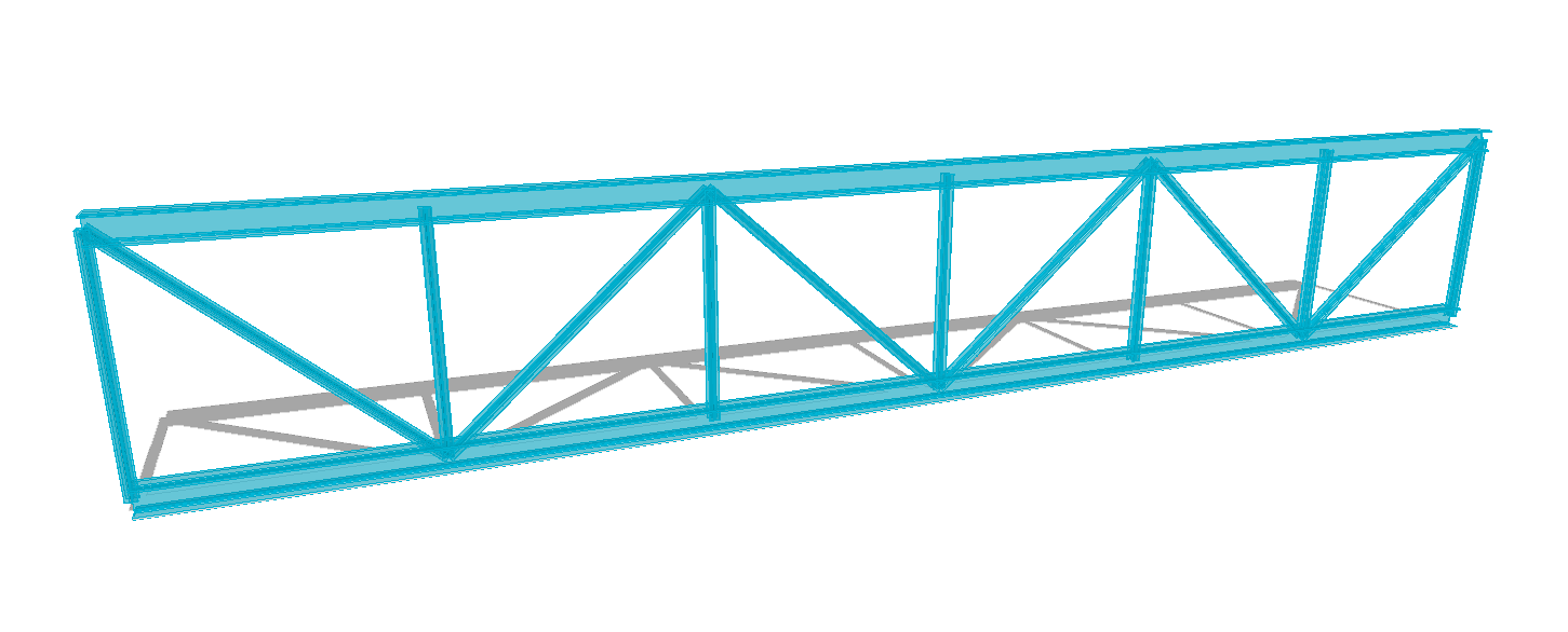
The “Hello World!” for parametric structural engineering. The Parametric Truss!
Challenge
Can you guess which nodes have I constrained?
If you give me the right response, I’ll create a custom example based on your request
Introduction
The article will highlight the most basic workflow necessary in order to create, analyse and read the results of a generic model.
The workflow consists in the definition of:
- Geometry
- Materials
- Sections
- Element such Bar, Supports
- Load
- Analysis
- Result Reader
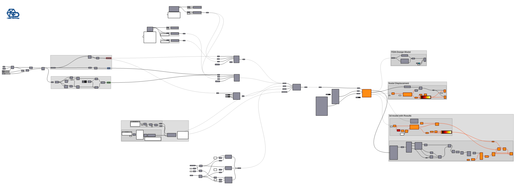
The picture below shows the entire workflow.
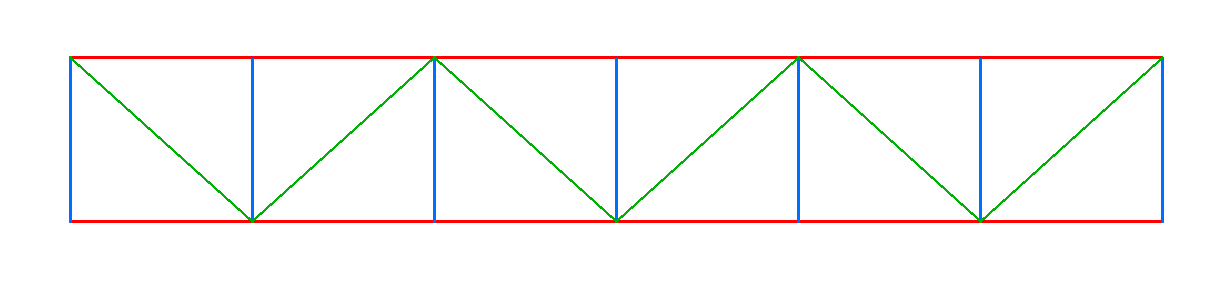
Geometry definition
The following script allows you to create a truss with diagonals.
The following parameters can be modified:
- Length
- Height
- Number of Subdivision
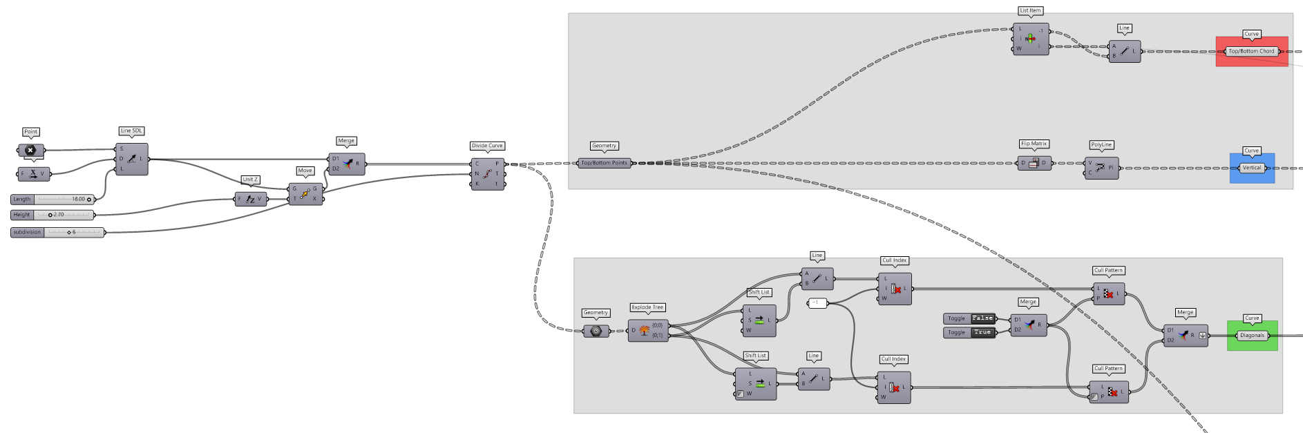
Modifying the parameters will generate a different geometry and therefore, it will be possible to understand their behaviours with the use of a single script. 😎
Pre-processing
The geometries (points, lines and meshes) need to be converted in mechanical elements and in order to do so, the objects require some additional information including:
- material
- section
- connectivity
Material definition
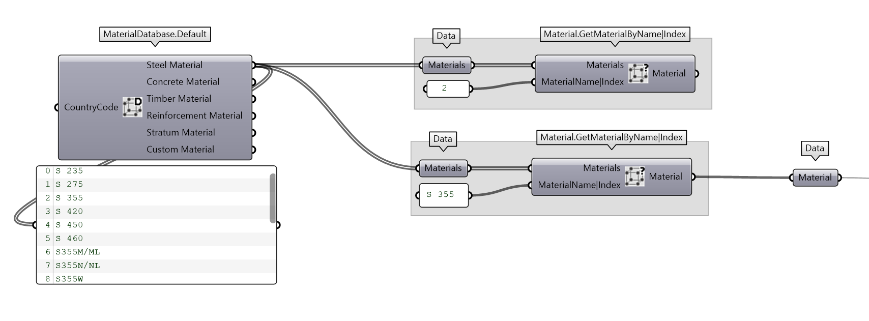
FEM-Design provide a list of material to choose from. MaterialDatabase.Default component will return some list grouped by material type.
The material can be selected using the provided Material.GetMaterialByName|Index. The material name can be seen directly from the output. It is up to you to decide if you want to use a string or int to select the desired material.
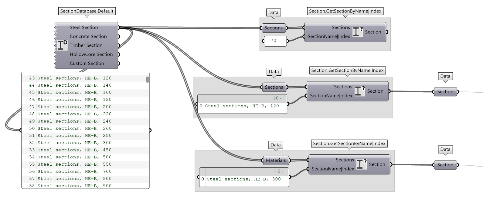
Section definition
The same workflow has been created to select a Section. SectionDatabase.Default component will return some list grouped by section type and Section.GetSectionByName|Index will help you in selecting the right section.
Great! 🎉
We have the minimum ingredients to convert a Line to a Bar.
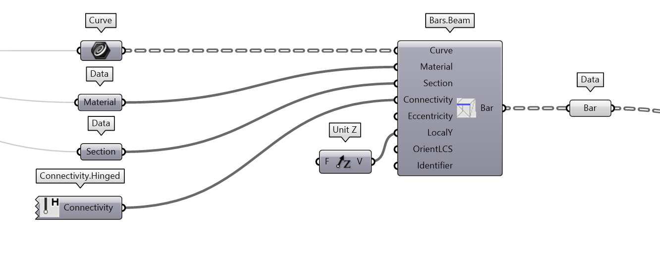
Element definition
Bar.Beam is the component necessary to create a Beam element. As you can see from the picture, material and section are plugged in the Bar.Beam component in their respective input. Additionally, you can see a Connectivity component which define the internal release of the element. By default, the connectivity is defined as Connectiviy.Rigid. For our example, Connectiviy.Hinged has been choosen.
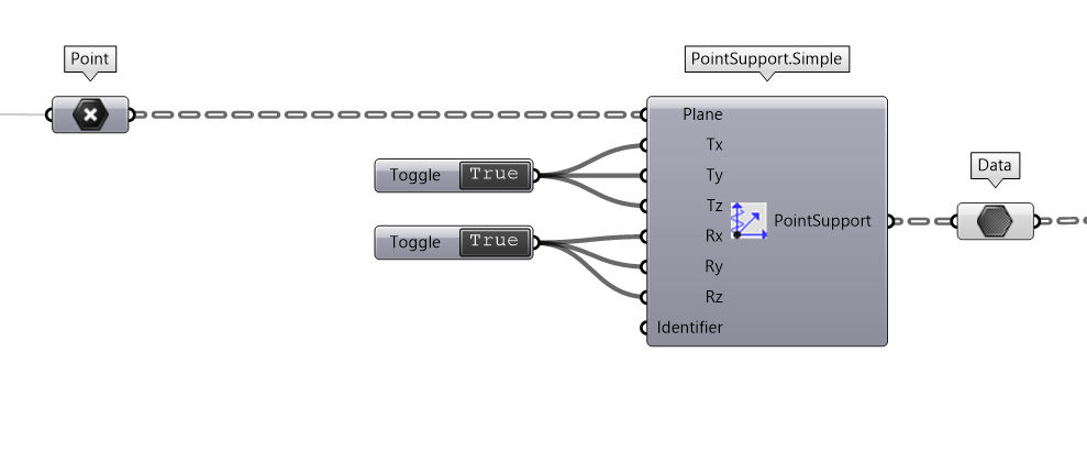
Constraint definition
Every structure needs to be anchored to gain stability. FEM-Design API provides you different way to define the PointSupport and some of them are ready to be use.

I personally like to define my anchors with PointSupport.Simple. It is the quickest way to define a generic support if you don’t require to check the uplift.
Loads
While I was a student, a teacher of mine use to told me: “Gravity Load never sleep” 💤
So let’s make sure to apply all the necessary loads!
PS: The article will show you only few type of loads. Make sure to check the load section and see what it is possible.
Load case definition
Loads have different intensity, different nature, different probability and different risk.
The nature of the load can be translate with the idea of LoadCase .
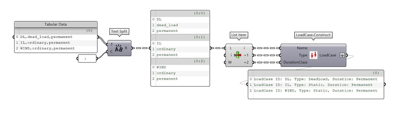
There are several way to create those and I wanted to show you two. The first option is to use a different component for every load case while the other option (more elegant) is to create a tabular data (it can be a a .csv file or plain text) from which we can read the values.
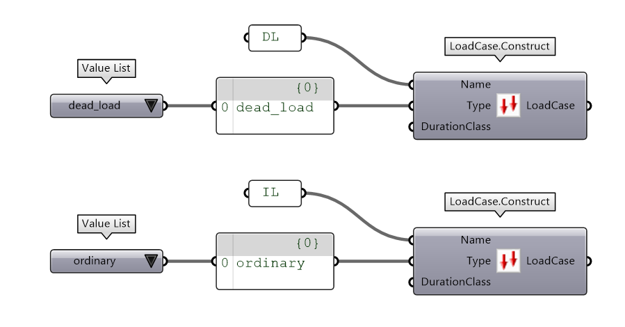
As you can see from the picture below, the approach is more scalable and it will have less spaghetti 🍝
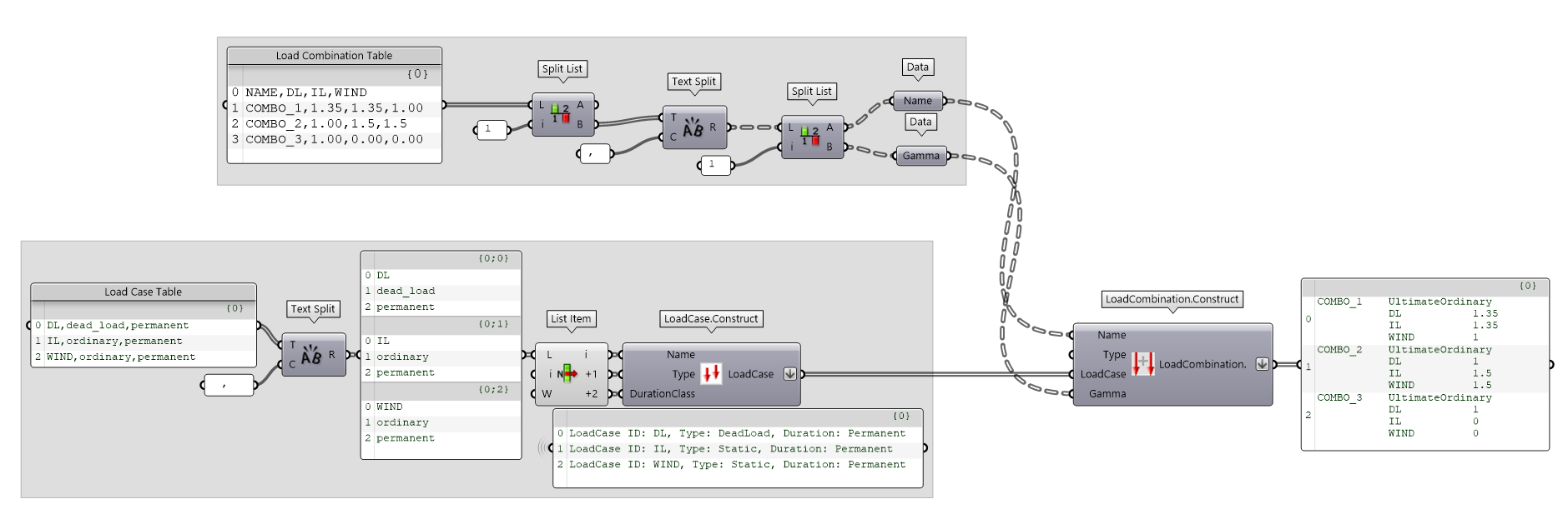
Load combination definition
LoadCombination are defining if the LoadCase should act together and their GammaFactor.
The easies way to create them is with the Table technique approach as you see in the picture below. I highly suggest you to tried in using my workflow. You should be satisfied.
From 21.4.0, it will be possible to see a custom visualisation of the object as it is shown in the white panels. It will be pretty easy to see if the input are read correctly.
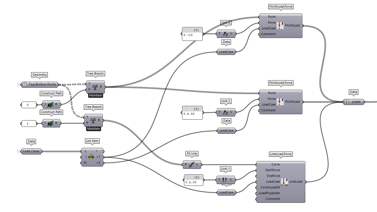
Load definition
In the following section, you can see how to apply some PointLoad.Force and LineLoad.Force.
Those components are the one which will define the intensity and location of the forces.
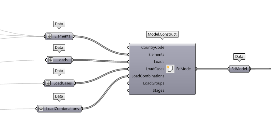
Model construct
As soon as you have defined all the ingredients, it will be time to combine them all together and Construct our FEM-Design model. Remember to flatten if you want to make sure to create only one model.
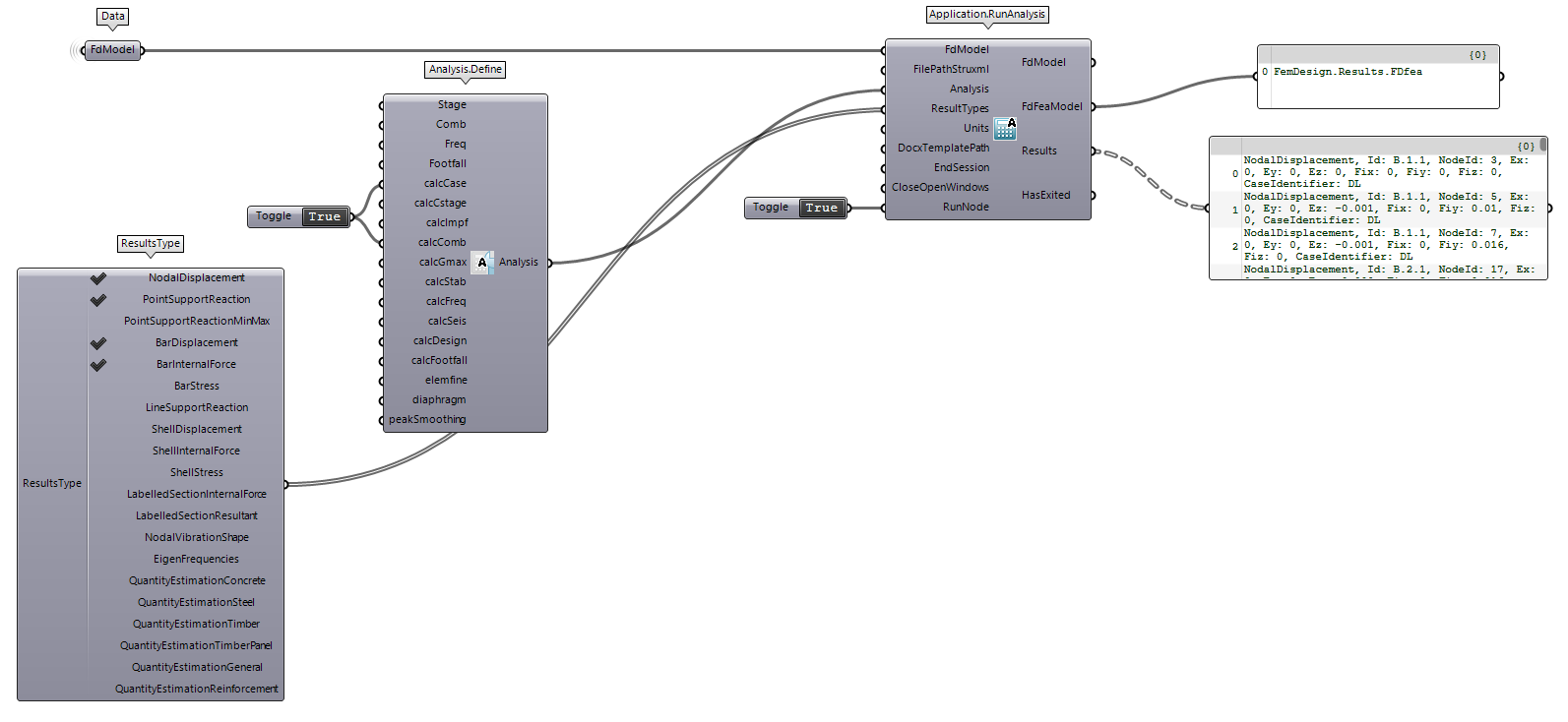
Analysis
It is finally time to prepare our model to be analyse with FEM-Design. Application.RunAnalysis is the component that will send our model to FEM-Design application and trigger the calculation.
Several analysis can be performed through the API but, in this case, we are only interested in LoadCase and LoadCombination solution.
There is also the option to read some results at the end of the calculation. ResultType component will show you what it is possible to extract. Feel free to contact us if you need something different.
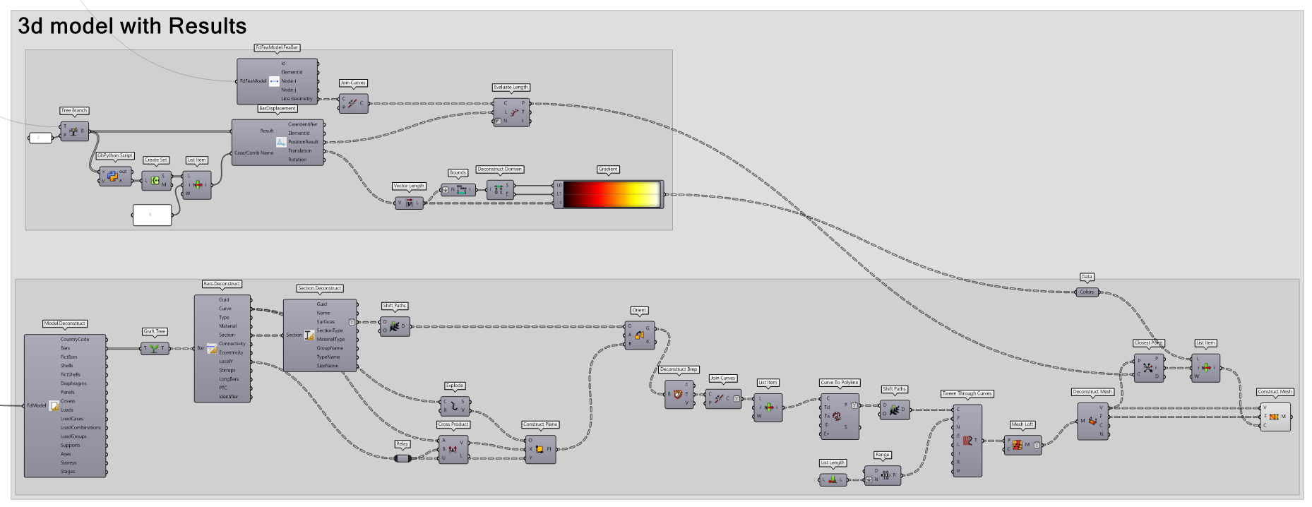
Post processing
It is finally time to investigate the behaviour of our Structural Model. The process of investigation can be done through the API reading the results.
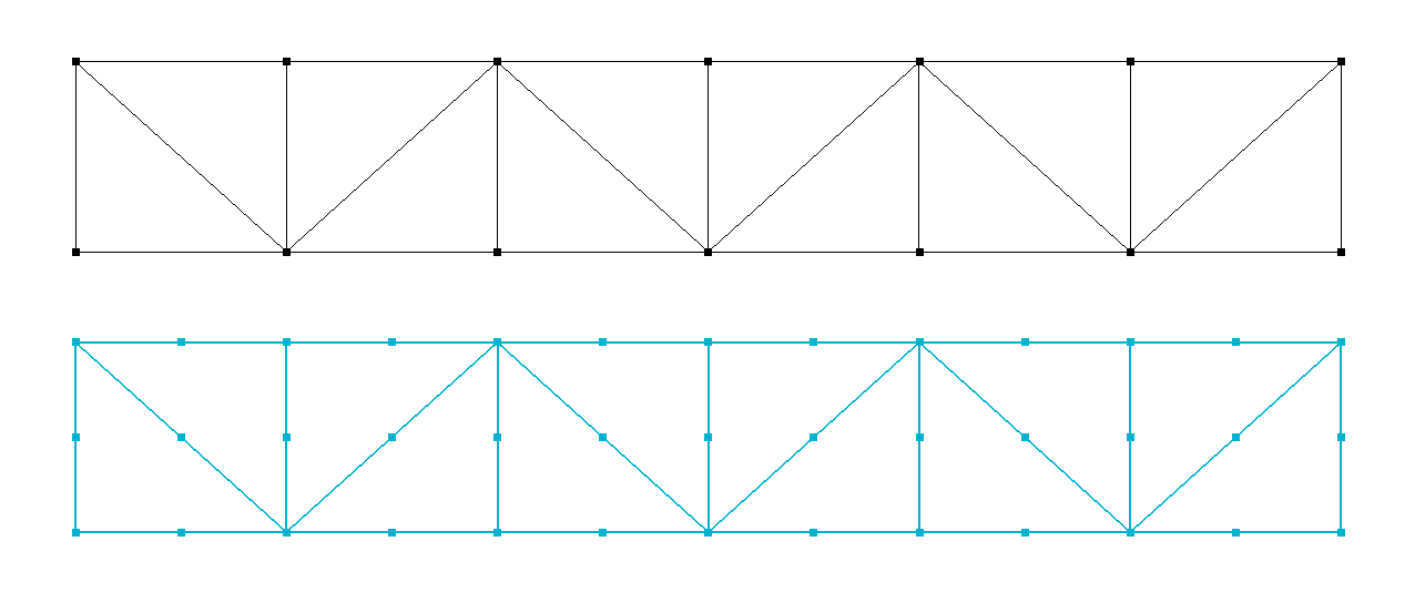
It is important to notice that FEM-Design will generate a Finite Element Model for his calculation and it is a good habit to see what it calculates. FdFeaModelallows you to check the geometry with minimum efforts.
FEA model geometry
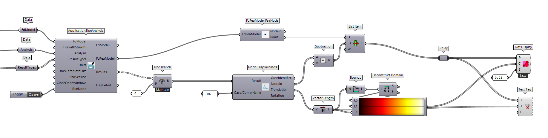
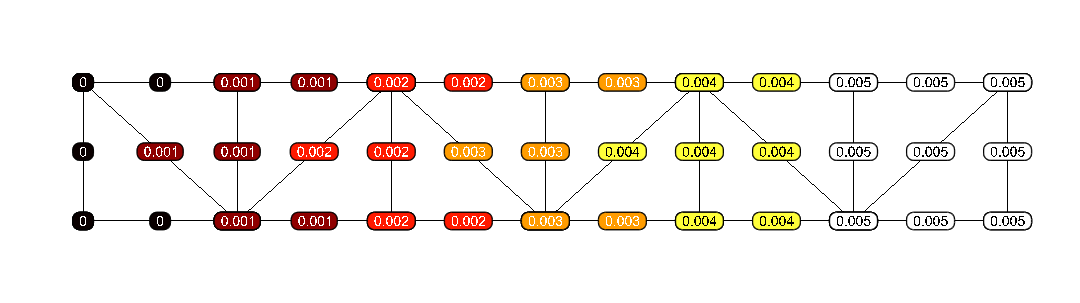
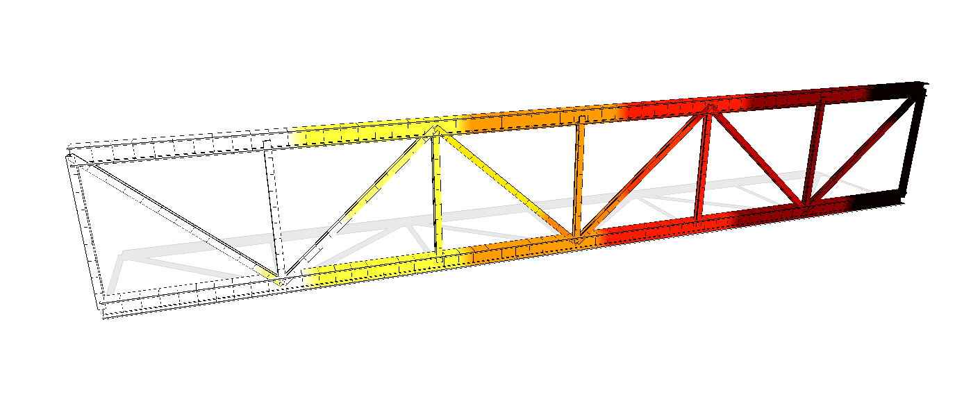
Results
It is time to see how to visualise some text on display. The picture below show you a simple way to see the nodal displacement with a Magma color map.
I want you to remind you that the process of visualising the result is one of the topic where the automatization should be done. Feel free to save the script and use it every time you need to visualise the nodal displacement. It is good habit to save those workflow as cluster so that you don’t need to create them from scratch all the time.
Bonus
It is not always necessary to represent our results to a 3d model. Most of time is enough to have numerical data on screen in form of text.
The following script is to highlight that with FEM-Design API is already possible to create some complex numerical visualisation. It does require some effort but it is definitely possible :)
Useful links
FEM-Design API developer are always ready to reply to the user concerns/issues.
Feel free to use one of the following link to reach out 🙂
🔗 Github
🔗 WikiFem