Topology optimisation
· 2 min read


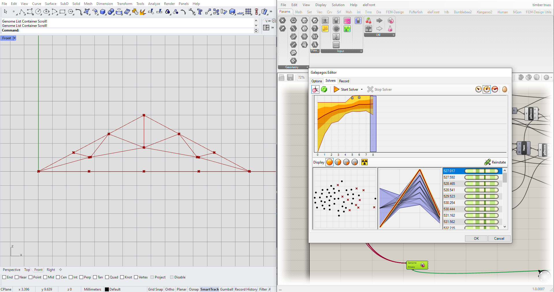
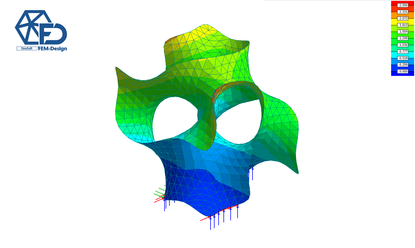
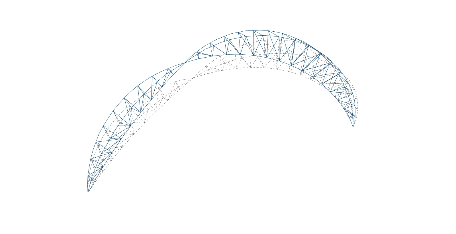
It’s time for some topology optimization! More specifically multivariable optimization of a parametric timber truss. 🤓
In this example I have created a timber truss with 4 variables that describe the shape of it. This is a very practical way of going about a topology optimization since you can limit the possible shapes due to production limitations to achieve an optimized structure that doesn’t look like a warped alien spaceship 🚀 😊