FdScript
Since FEM-Design 17.01.001, we support a basic automation workflow through scripting. It is capable to load/save file, execute analysis calculation and create outputs as .csv list or .docx documentation. Using scripting you can batch-analyze models created and execute long calculations during the night.
You can download a definition used in this section from here 👉fdscript example
The .fdscript requires the filepath to be absolute, i.e., starting from the drive letter. Relative paths are not supported.
Replace the placeholders (e.g., e:\x.struxml) in the example script with actual file paths on your computer before running the script.
Concept
The installation of FEM-Design creates the example.fdscript in the templates folder. The latter can be used as a starting point of custom scripts since it has all the commands intended for users and useful comments on how to proceed.
fdscript
<?xml version="1.0" encoding="UTF-8"?>
<fdscript xmlns:xsi="http://www.w3.org/2001/XMLSchema-instance" xsi:noNamespaceSchemaLocation="fdscript.xsd">
  <!-- SCRIPT HEADER  ==================================================================================  -->
  <fdscriptheader>
    <title>FEM-Design example script</title>
    <version>2100</version>
    <module>SFRAME</module>
    <!-- log file where warnings from calculation and other interesting entries may appear -->
    <logfile>e:\x.log</logfile>
  </fdscriptheader>


  <!-- command for menu file/open use the filename with extension -->
  <cmdopen command="; CXL CS2SHELL OPEN">
    <filename>e:\x.struxml</filename>
  </cmdopen>


  <!-- command for calculation on Analysis tab  -->
  <cmduser command="; CXL $MODULE RESMODE" />
  <cmdcalculation command="; CXL $MODULE CALC">
    <analysis
      calcCase = "1"
      calcCstage = "0"
      calcImpf = "0"
      calcComb = "1"
      calcGmax = "0"
      calcStab = "0"
      calcFreq = "0"
      calcSeis = "0"
      calcFootfall = "0"
      calcMovingLoad = "0"
      calcBedding = "0"
      calcThGroundAcc = "0"
      calcThExforce = "0"
      calcDesign = "0"

      elemfine = "1"
      diaphragm = "0"
      peaksmoothing = "1"
    >
      <stage ghost = "0" />
      <comb
        NLEmaxiter = "30"

        PLdefloadstep = "20"
        PLminloadstep = "2"
        PLmaxeqiter = "30"

        NLSMohr = "1"
        NLSinitloadstep = "10"
        NLSminloadstep = "10"
        NLSactiveelemratio = "5"
        NLSplasticelemratio = "5"

        CRloadstep = "20"
        CRmaxiter = "30"
        CRstifferror = "2"
      >
        <combitem
          ImpfRqd = "0"
          StabRqd = "0"

          NLE = "0"
          PL = "0"
          NLS = "0"
          Cr = "0"
          f2nd = "0"
          Im = "0"
          Waterlevel = "0"
        />
      <freq
        Numshapes = "2"
        MaxSturm = "0"
        X = "1"
        Y = "1"
        Z = "1"
        top = "0.0"
        AutoIter = "5"
        NormUnit = "0"
      />
      <footfall TopOfSubstructure = "-0.01" />
      <bedding
        Ldcomb = "a"
        Meshprep = "0"
        Stiff_X = "0.5"
        Stiff_Y = "0.5"
      />
    </analysis>
  </cmdcalculation>


  <!-- command for calculation on RC design tab for load combinations, autodesign may be false if reinforcement present in input file -->
 <cmduser command="; CXL $MODULE RCDESIGN" />
 <cmdcalculation command="; CXL $MODULE CALC">
  <design>
   <cmax />
   <autodesign>true</autodesign>
    <check>true</check>
  </design>
 </cmdcalculation>


  <!-- command for calculation on steel design tab, set autodesign to true if needed  -->
 <cmduser command="; CXL $MODULE STEELDESIGN" />
 <cmdcalculation command="; CXL $MODULE CALC">
  <design>
   <cmax />
   <autodesign>false</autodesign>
    <check>true</check>
  </design>
 </cmdcalculation>


  <!-- command to generate csv file output as from list panel batch, use proper filenames and "1" if want the checkbox option   -->
  <cmdlistgen command="$ MODULECOM LISTGEN" bscfile="e:\x.bsc" outfile="e:\x.csv" regional="0" fillcells="0" headers="0" />
  <cmdlistgen command="$ MODULECOM LISTGEN" bscfile="e:\y.bsc" outfile="e:\y.csv" regional="0" fillcells="0" headers="0" />
  <!-- repeat for additional batches if i.e each has just one table  -->


  <!-- command to make documentation from doc template   -->
  <cmdchild>e:\x.dsc</cmdchild>


  <!-- command to export documantation to .docx   -->
  <cmdsavedocx command="$ DOC SAVEDOCX">
    <filename>e:\x.docx</filename>
  </cmdsavedocx>


  <!-- command to save the model, use extension with filename!  -->
  <cmdsave command="; CXL CS2SHELL SAVE">
    <filename>e:\x1.str</filename>
  </cmdsave>


  <!-- command to quit the program -->
  <cmdendsession/>


  <!-- END SESSION 	===================================================================================  -->
</fdscript>
The example script can be edited using notepad but it is more convenient to use a code editor such as Visual Studio Code.
Fdscript can be generated and run programmatically using the python package. The following sections explain the use of the cmd/command that can be use within the python package.
Procedure
Log file
Enter the location for the log file that will contain all the information about performed calculations, errors and warnings. Always use absolute path for files.
<fdscriptheader>
    <title>FEM-Design example script</title>
    <version>2100</version>
    <module>SFRAME</module>
    <logfile>e:\x.log</logfile>
</fdscriptheader>
Open model
Enter the location of the model that will be executed by the Run script function. The model can be saved both as .struxml or .str file type.
<cmdopen command="; CXL CS2SHELL OPEN">
    <filename>e:\x.struxml</filename>
</cmdopen>
Analysis
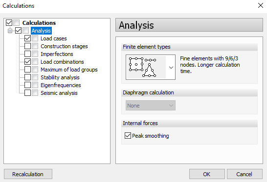
Select the type of analysis calculations that you wish to perform running the script. This is done by typing "1" or "0" next to the corresponding calculation type in the script example, where "1" means to perform that calculations. The listed calculation types exactly correspond to the order of calculations in the Calculation dialog in FEM-Design.

<cmduser command="; CXL $MODULE RESMODE" />
<cmdcalculation command="; CXL $MODULE CALC">
<analysis
    calcCase = "1"
    calcCstage = "0"
    calcImpf = "0"
    calcComb = "1"
    calcGmax = "0"
    calcStab = "0"
    calcFreq = "0"
    calcSeis = "0"
    calcFootfall = "0"
    calcMovingLoad = "0"
    calcBedding = "0"
    calcThGroundAcc = "0"
    calcThExforce = "0"
    calcDesign = "0"

    elemfine = "1"
    diaphragm = "0"
    peaksmoothing = "1">
</analysis>
</cmdcalculation>
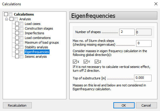
The example script contains more options to set up calculation parameters, for example details of construction stages analysis, Eigenfrequencies or calculation options for load combinations calculations.

<freq
    Numshapes = "2"
    MaxSturm = "0"
    X = "1"
    Y = "1"
    Z = "1"
    top = "0.0"
    AutoIter = "0"
    NormUnit = "0"/>

<footfall   TopOfSubstructure = "-0.01" />
</analysis>
Design
Select whether you want to perform Auto design or Check calculations, by typing "false" or "true" in the corresponding design module part of the script.
<cmduser command="; CXL $MODULE RCDESIGN" />
<cmdcalculation command="; CXL $MODULE CALC">
    <design>
        <cmax />
        <autodesign>true</autodesign>
    <check>true</check>
    </design>
</cmdcalculation>

<cmduser command="; CXL $MODULE STEELDESIGN" />
<cmdcalculation command="; CXL $MODULE CALC">
    <design>
        <cmax />
        <autodesign>false</autodesign>
    <check>true</check>
    </design>
</cmdcalculation>
Create design group
<cmddesgroup command="$ CODE_COM DESGROUP"
      name="A" color="0" force="false" type="STBAR">
  <GUID>2e290437-e86a-4e36-af7d-acde6a6146c8</GUID>
  <GUID>2cba9c00-255d-4258-94fb-f164aafff214</GUID>
</cmddesgroup>
valid types are:
"FNISOLATED", "FNWALL", "FNSLAB", "RCSURFLONG", "RCSURFSHEAR", "RCPUNCH", "STBARSHELL", "STJOINT", "TMBAR", "TMPANEL", "TMPANELCLT", "MS", "COCOLUMN", "CODELTABEAM", "RCBAR", "RCHIDDENBAR", "STBAR", "STFIRE", "TMFIRE", "CLTFIRE"
without force the group must not already exist.
To delete a group use force="true" and empty guid list
All entities must be conforming to the group type.
remember that you must pass analytical entities!
Apply design changes
Command to force to apply design changes after calculating with autodesign
<cmduser command="; CXL FEM $CODE(DESCHANGESAPPLY)" />
Generate csv output file
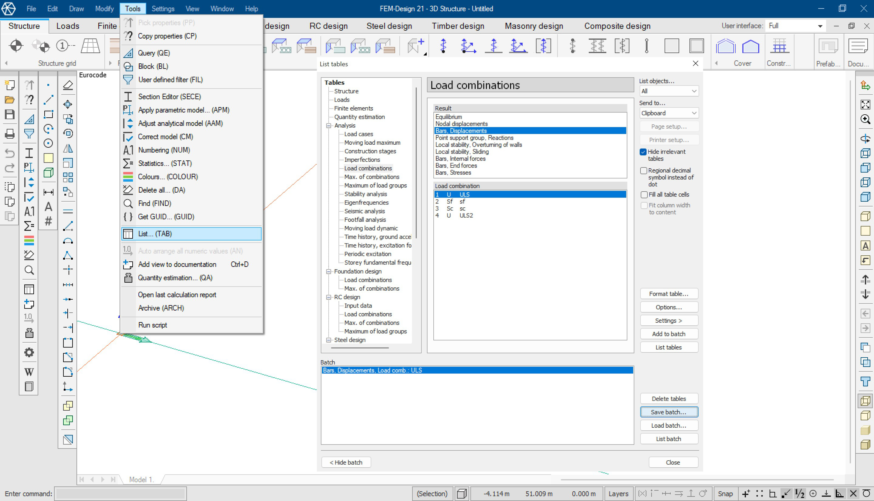
It is possible to generate a csv file from List tables batch. First, select all the tables in List tables dialog in FEM-Design and save it as a batch file (.bsc).

Then replace the name and location of the batch file (.bsc) and output file (.csv) in the script example.
<cmdlistgen command="$ MODULECOM LISTGEN" bscfile="e:\x.bsc" outfile="e:\x.csv" regional="0" fillcells="0" headers="0" />
Set project description
<cmdprojdescr command="$ MODULECOM PROJDESCR"
  read="0" reset="0"
  szProject="t1"
  szDescription="t2"
  szDesigner="t3"
  szSignature="t4"
  szComment="t5">
    <item id="a" txt="a_txt"/>
    <item id="b" txt="b_txt"/>
</cmdprojdescr>
Global configurations
<cmdglobalcfg command="$ FEM $CODE(GLOBALCFG)">
  <soil_calculation
    fSoilAsSolid = "0"
  />
  <mesh_general
    fAdjustToLoads = "0"
  />
  <mesh_elements
    fElemCalcRegion = "1"
    rElemSizeDiv = "6.0"
    fCorrectToMinDivNum = "1"
    sDefaultDivision = "2"
    rDefaultAngle = "15.0"
    sDefaultEdgeDivision = "1"
  />
  <mesh_functions
    fRefineLocally = "1"
    sRefineMaxStepNum = "5"
    fMaxIterWarning = "0"
    fReduceSize = "1"
    sSmoothStepNum = "3"
    fCheckMeshGeom = "1"
    rCheckGeomMinAngle = "10.0"
    rCheckGeomMaxAngle = "170.0"
    rCheckGeomMaxSideRatio = "8.0"
    fCheckMeshOverlap = "1"
    fCheckMeshTopology = "1"
  />
  <mesh_prepare
      fAutoRegen = "1"
      fThPeak = "1"
      fThBeam = "0"
      fThColumn = "1"
      fThTruss = "0"
      fThFicBeam = "0"
      fThFreeEdge = "0"
      fThRegionBorder = "0"
      fThSuppPt = "1"
      fThSuppLn = "0"
      fThSuppSf = "0"
      fThEdgeConn = "0"
      fThConnPt = "0"
      fThConnLn = "0"
      fThConnSf = "0"
      fThLoadPt = "0"
      fThLoadLn = "0"
      fThLoadSf = "0"
      fThFixPt = "0"
      fThFixLn = "0"
      fAutoRebuild = "1"
      fAutoSmooth = "1"
      fAutoCheck = "0"
  />
  <peaksm_method
      sPeakFormFunc_M = "1"
      sPeakFormFunc_N = "1"
      sPeakFormFunc_V = "1"
  />
  <peaksm_auto
      fPeakBeam = "0"
      fPeakColumn = "1"
      fPeakTruss = "0"
      fPeakFicBeam = "0"
      fPeakPlate = "0"
      fPeakWall = "0"
      fPeakFicShell = "0"
      fPeakSuppPt = "1"
      fPeakSuppLn = "0"
      fPeakSuppSf = "0"
      fPeakConnPt = "0"
      fPeakConnLn = "0"
      fPeakConnSf = "0"
      rPeakFactor = "0.5"
  />
</cmdglobalcfg>
Calculation\Design configurations
The API allows to set the design and configuration parameters specifying the <CONFIG> elements.
Use command in femdesign to dump existing config as starting point so that you can modify them subsequently:
; CXL MODULECOM WXMLCFG:C:\temp\cfg.xml
The command will generate a file in temp. Make sure that the folder exist.
Depending on the elements present in the model, the generated xml file will have different attributes.
The meaning of most settings can be figured out by looking at the related dialog. Checkboxes are boolean, radiobuttons/list selection provide 0-based index.
cfg.xml
  <?xml version="1.0" encoding="UTF-8"?>
  <configs>
    <CONFIG fIgnoreAnnexForShearStrength="false" StripeWidth="1" type="CCMSCONFIG"></CONFIG>
    <CONFIG type="CCCOCONFIG"></CONFIG>

    <!-- EUROCODE FOUNDATION CONFIG -->
    <CONFIG acc_Au_0="1.35" acc_Au_1="1" acc_c_0="1" acc_c_1="1" acc_cu_0="1" acc_cu_1="1" acc_gamma_0="1" acc_gamma_1="1" acc_phi_0="1" acc_phi_1="1" acc_Rh_0="1" acc_Rh_1="1" acc_Rh_2="1" acc_Rv_0="1" acc_Rv_1="1" acc_Rv_2="1" method_0="0" method_1="0" seis_Au_0="1.35" seis_Au_1="1" seis_c_0="1" seis_c_1="1.25" seis_cu_0="1" seis_cu_1="1.4" seis_gamma_0="1" seis_gamma_1="1" seis_phi_0="1" seis_phi_1="1.25" seis_Rh_0="1" seis_Rh_1="1.1" seis_Rh_2="1" seis_Rv_0="1" seis_Rv_1="1.4" seis_Rv_2="1" settlement_fAlpha="true" settlement_fBeta="false" settlement_fDelta_l="true" settlement_fDelta_s="false" settlement_fOmega="true" settlement_fTheta="true" settlement_rAlpha="0.0066666" settlement_rBeta="0.0066666" settlement_rDelta_l="0.0033333" settlement_rDelta_s="0.05" settlement_rOmega="0.0066666" settlement_rTheta="0.0066666" type="ECFNCONFIG" ult_Au_0="1.35" ult_Au_1="1" ult_c_0="1" ult_c_1="1.25" ult_cu_0="1" ult_cu_1="1.4" ult_gamma_0="1" ult_gamma_1="1" ult_phi_0="1" ult_phi_1="1.25" ult_Rh_0="1" ult_Rh_1="1.1" ult_Rh_2="1" ult_Rv_0="1" ult_Rv_1="1.4" ult_Rv_2="1"></CONFIG>

    <!-- EUROCODE STEEL CONFIG -->
    <CONFIG sInteraction="0" type="ECSTCONFIG"></CONFIG>

    <!-- DESIGN PARAMETERS STEEL BAR -->
    <CONFIG LimitUtilization="0.8" type="CCDESPARAMBARST" vSection_csec_0="6bd231aa-f0f8-4f40-a212-65f8bbe0ea49" vSection_csec_1="e26954f6-ee0c-481d-9bbb-94b69f102ab6" vSection_csec_10="3dc3126b-8efb-4aa9-811f-0fdc94c81d9c" vSection_csec_11="8510189c-f81b-45b6-9365-7a27d9965865" vSection_csec_12="9e039d75-0074-4925-96eb-4ead4282a5c7" vSection_csec_13="ac52e18d-2c1d-4bba-a4da-660b9214e7bf" vSection_csec_14="7a202a33-ee6a-41f5-a6f1-e59bb9b69b71" vSection_csec_15="a8c7381a-f13d-455b-bfce-9f3e592eef2f" vSection_csec_16="c95a72e3-8a43-4681-9433-3f7b36e99cfa" vSection_csec_17="5923c3e8-1697-4cbb-bcbe-00e70b9856a8" vSection_csec_18="89ad3214-bd6a-4ada-9739-688341f117ad" vSection_csec_19="8d2dc589-107f-4f54-bed2-8aa51cf69178" vSection_csec_2="77991d14-b5f1-4981-8344-30c503fc619f" vSection_csec_20="35947b75-4bfd-4b5a-bb43-2881435ad046" vSection_csec_21="efa014a1-1ed0-4d91-a1dc-babe7d70ebc3" vSection_csec_22="115d5ec8-3041-46bd-8ecd-4268492b7670" vSection_csec_23="9997e571-152b-4680-bee8-f5f668e819ba" vSection_csec_3="7497b835-4e8f-4f7e-a81b-5d2b3a6addd4" vSection_csec_4="3ec86e35-9e3f-46a6-872a-179fc055be90" vSection_csec_5="1232c45d-2a0e-424e-afb4-2c4b710cfb3a" vSection_csec_6="06f0f517-d448-4e7e-bd66-5b360eb6a3df" vSection_csec_7="bbbb7a06-3600-4651-90e0-e0f55f8ec0eb" vSection_csec_8="c2193eb3-50c2-4370-9272-69b348fc3856" vSection_csec_9="51d3e98c-d13c-40fa-a7be-5be132b82750" vSection_itemcnt="24"></CONFIG>

    <!-- EUROCODE CALCULATION PARAMETERS STEEL BAR -->
    <CONFIG aBucklingCurve_fx1="-1" aBucklingCurve_fx2="-1" aBucklingCurve_ltb="-1" aBucklingCurve_ltt="-1" aBucklingCurve_tf="-1" CheckResistanceOnly="1" class4Ignored="1" convergencyratio="1" fLatTorBuckGen="1" fLatTorBuckGenSpecForI="0" maxIterStep="50" plasticIgnored="0" rStep="0.5" s2ndOrder="1" type="ECCALCPARAMBARST" UseEqation6_41="0"></CONFIG>

    <!-- EUROCODE CONCRETE CONFIG -->
    <CONFIG s2ndOrder="0" type="ECRCCONFIG"></CONFIG>

    <!-- DESIGN PARAMETERS CONCRETE BAR -->
    <CONFIG desparam_fSymmCirc="0" desparam_fSymmY="0" desparam_fSymmZ="0" desparam_hfVibrator="" desparam_hSteel_aux="0" desparam_hSteel_long="0" desparam_hSteel_stir="0" desparam_lProfile_aux="1" desparam_lProfile_long="1" desparam_lProfile_stir="1" desparam_rAggregate="20" desparam_rDiam_aux="8" desparam_rDiam_long_aux="16" desparam_rDiam_stir="8" desparam_vCover_itemcnt="1" desparam_vCover_r_0="20" LimitUtilization="1" type="CCDESPARAMBARRCREAL" vSection_csec_0="2c14a0a2-63c8-4586-a30e-97b20ea376fb" vSection_itemcnt="1"></CONFIG>

    <!-- EUROCODE CALCULATION PARAMETERS CONCRETE BAR -->
    <CONFIG aEcc_Imperfection="0" aEcc_Minimal="0" aEcc_SecondOrder="0" afEcc_Imperfection="TRUE" afEcc_Minimal="TRUE" afEcc_SecondOrder="TRUE" cot_theta="1.25" csf="1" fColumn="FALSE" fCompReinf="0" fEccUdImpf="FALSE" fEccUdMin="FALSE" fIgnoreTorsion="FALSE" firestdRC_dt="5" firestdRC_epsf="1" firestdRC_epsm="0.7" firestdRC_fCheckShearAndTorsion="0" firestdRC_fConsiderInAnchorageLength="0" firestdRC_fDesignForFire="1" firestdRC_lAggregateType="0" firestdRC_lDesignMethod="1" firestdRC_lManufactureType="0" firestdRC_lMeshDivisor="9" firestdRC_lMoistureContent="1" firestdRC_lSteelClass="0" firestdRC_lThermalConductivityLimit="0" firestdRC_Phi="1" firestdRC_rConcDensity="2300" firestdRC_TempCurve="0" firestdRC_treq="120" fMomentforlambdalim="FALSE" rCrackLimit="1" rEccUdImpf0="0" rEccUdImpf1="0" rEccUdMin0="0" rEccUdMin1="0" rStep="0.5" s2ndOrder="1" type="ECCALCPARAMBARRC"></CONFIG>

    <!-- EUROCODE CALCULATION PARAMETERS CONCRETE SHELL -->
    <CONFIG afShellBucklingEccApplied_Imperfection="TRUE" afShellBucklingEccApplied_Minimal="TRUE" afShellBucklingEccApplied_SecondOrder="TRUE" arEccUdAdd0="0" arEccUdAdd1="0" arEccUdMin0="0" arEccUdMin1="0" csf="1" face_0_fXOnTop="0" face_0_hSteel_x="0" face_0_hSteel_y="0" face_0_rCover_x="20" face_0_rCover_y="30" face_0_rCwLimit="0.4" face_0_rDiam_x="10" face_0_rDiam_y="10" face_0_rEcc="0" face_1_fXOnTop="0" face_1_hSteel_x="0" face_1_hSteel_y="0" face_1_rCover_x="20" face_1_rCover_y="30" face_1_rCwLimit="0.4" face_1_rDiam_x="10" face_1_rDiam_y="10" face_1_rEcc="0" fCompressed="0" fDescartes="1" firestdRCShell_dt="5" firestdRCShell_epsf="1" firestdRCShell_epsm="0.7" firestdRCShell_fCheckShellBuckling="0" firestdRCShell_lAggregateType="0" firestdRCShell_lDesignMethod="0" firestdRCShell_lManufactureType="0" firestdRCShell_lMeshDivisor="9" firestdRCShell_lMoistureContent="1" firestdRCShell_lSteelClass="0" firestdRCShell_lThermalConductivityLimit="0" firestdRCShell_Phi="1" firestdRCShell_rConcDensity="2300" firestdRCShell_TempCurve="0" firestdRCShell_treq="120" fMinReinf="1" fSingleLayer="false" lb="1.3385" type="ECCALCPARAMSHELLRC"></CONFIG>

    <!-- EUROCODE CALCULATION PARAMETERS CONCRETE SHELL SHEAR -->
    <CONFIG cot_theta="1" hSteel="0" type="ECCALCPARAMSHELLRCSHEAR"></CONFIG>

    <!-- DESIGN PARAMETERS CONCRETE SHELL -->
    <CONFIG face_0_fBaseNet="TRUE" face_0_fLockSpace="TRUE" face_0_Lay_0_0_hSteel="0" face_0_Lay_0_0_rDiam="10" face_0_Lay_0_0_rMaxSpace="300" face_0_Lay_0_0_rMinSpace="50" face_0_Lay_0_0_rRectBandMin="0" face_0_Lay_0_0_rRectStep="1000" face_0_Lay_0_0_rRound="100" face_0_Lay_0_0_rSpace="150" face_0_Lay_0_0_rSpaceStep="50" face_0_Lay_0_0_sMethod="1" face_0_Lay_0_1_hSteel="0" face_0_Lay_0_1_rDiam="10" face_0_Lay_0_1_rMaxSpace="300" face_0_Lay_0_1_rMinSpace="50" face_0_Lay_0_1_rRectBandMin="0" face_0_Lay_0_1_rRectStep="1000" face_0_Lay_0_1_rRound="100" face_0_Lay_0_1_rSpace="150" face_0_Lay_0_1_rSpaceStep="50" face_0_Lay_0_1_sMethod="1" face_0_Lay_1_0_hSteel="0" face_0_Lay_1_0_rDiam="10" face_0_Lay_1_0_rMaxSpace="300" face_0_Lay_1_0_rMinSpace="50" face_0_Lay_1_0_rRectBandMin="0" face_0_Lay_1_0_rRectStep="1000" face_0_Lay_1_0_rRound="100" face_0_Lay_1_0_rSpace="150" face_0_Lay_1_0_rSpaceStep="50" face_0_Lay_1_0_sMethod="0" face_0_Lay_1_1_hSteel="0" face_0_Lay_1_1_rDiam="10" face_0_Lay_1_1_rMaxSpace="300" face_0_Lay_1_1_rMinSpace="50" face_0_Lay_1_1_rRectBandMin="0" face_0_Lay_1_1_rRectStep="1000" face_0_Lay_1_1_rRound="100" face_0_Lay_1_1_rSpace="150" face_0_Lay_1_1_rSpaceStep="50" face_0_Lay_1_1_sMethod="0" face_0_Lay_2_0_hSteel="0" face_0_Lay_2_0_rDiam="12" face_0_Lay_2_0_rMaxSpace="300" face_0_Lay_2_0_rMinSpace="50" face_0_Lay_2_0_rRectBandMin="0" face_0_Lay_2_0_rRectStep="1000" face_0_Lay_2_0_rRound="100" face_0_Lay_2_0_rSpace="150" face_0_Lay_2_0_rSpaceStep="50" face_0_Lay_2_0_sMethod="1" face_0_Lay_2_1_hSteel="0" face_0_Lay_2_1_rDiam="12" face_0_Lay_2_1_rMaxSpace="300" face_0_Lay_2_1_rMinSpace="50" face_0_Lay_2_1_rRectBandMin="0" face_0_Lay_2_1_rRectStep="1000" face_0_Lay_2_1_rRound="100" face_0_Lay_2_1_rSpace="150" face_0_Lay_2_1_rSpaceStep="50" face_0_Lay_2_1_sMethod="1" face_1_fBaseNet="FALSE" face_1_fLockSpace="TRUE" face_1_Lay_0_0_hSteel="0" face_1_Lay_0_0_rDiam="10" face_1_Lay_0_0_rMaxSpace="300" face_1_Lay_0_0_rMinSpace="50" face_1_Lay_0_0_rRectBandMin="0" face_1_Lay_0_0_rRectStep="1000" face_1_Lay_0_0_rRound="100" face_1_Lay_0_0_rSpace="150" face_1_Lay_0_0_rSpaceStep="50" face_1_Lay_0_0_sMethod="1" face_1_Lay_0_1_hSteel="0" face_1_Lay_0_1_rDiam="10" face_1_Lay_0_1_rMaxSpace="300" face_1_Lay_0_1_rMinSpace="50" face_1_Lay_0_1_rRectBandMin="0" face_1_Lay_0_1_rRectStep="1000" face_1_Lay_0_1_rRound="100" face_1_Lay_0_1_rSpace="150" face_1_Lay_0_1_rSpaceStep="50" face_1_Lay_0_1_sMethod="1" face_1_Lay_1_0_hSteel="0" face_1_Lay_1_0_rDiam="10" face_1_Lay_1_0_rMaxSpace="300" face_1_Lay_1_0_rMinSpace="50" face_1_Lay_1_0_rRectBandMin="0" face_1_Lay_1_0_rRectStep="1000" face_1_Lay_1_0_rRound="100" face_1_Lay_1_0_rSpace="150" face_1_Lay_1_0_rSpaceStep="50" face_1_Lay_1_0_sMethod="0" face_1_Lay_1_1_hSteel="0" face_1_Lay_1_1_rDiam="10" face_1_Lay_1_1_rMaxSpace="300" face_1_Lay_1_1_rMinSpace="50" face_1_Lay_1_1_rRectBandMin="0" face_1_Lay_1_1_rRectStep="1000" face_1_Lay_1_1_rRound="100" face_1_Lay_1_1_rSpace="150" face_1_Lay_1_1_rSpaceStep="50" face_1_Lay_1_1_sMethod="0" face_1_Lay_2_0_hSteel="0" face_1_Lay_2_0_rDiam="12" face_1_Lay_2_0_rMaxSpace="300" face_1_Lay_2_0_rMinSpace="50" face_1_Lay_2_0_rRectBandMin="0" face_1_Lay_2_0_rRectStep="1000" face_1_Lay_2_0_rRound="100" face_1_Lay_2_0_rSpace="150" face_1_Lay_2_0_rSpaceStep="50" face_1_Lay_2_0_sMethod="1" face_1_Lay_2_1_dbDiam_itemcnt="0" face_1_Lay_2_1_hSteel="0" face_1_Lay_2_1_rDiam="12" face_1_Lay_2_1_rMaxSpace="300" face_1_Lay_2_1_rMinSpace="50" face_1_Lay_2_1_rRectBandMin="0" face_1_Lay_2_1_rRectStep="1000" face_1_Lay_2_1_rRound="100" face_1_Lay_2_1_rSpace="150" face_1_Lay_2_1_rSpaceStep="50" face_1_Lay_2_1_sMethod="1" LimitUtilization="1" type="CCDESPARAMSHELLRC"></CONFIG>

    <!-- DESIGN PARAMETERS CONCRETE SHELL SHEAR -->
    <CONFIG dbDiam_DbDiam_0="4" dbDiam_DbDiam_1="6" dbDiam_DbDiam_10="25" dbDiam_DbDiam_11="30" dbDiam_DbDiam_12="32" dbDiam_DbDiam_13="35" dbDiam_DbDiam_14="40" dbDiam_DbDiam_2="8" dbDiam_DbDiam_3="10" dbDiam_DbDiam_4="12" dbDiam_DbDiam_5="14" dbDiam_DbDiam_6="16" dbDiam_DbDiam_7="18" dbDiam_DbDiam_8="20" dbDiam_DbDiam_9="22" dbDiam_itemcnt="15" fUniformDiameter="1" hSteel="0" LimitUtilization="1" rRectBandMin="0" rRectStep="1000" rSpaceX="150" rSpaceY="150" sMethod="1" sSpacingMethod="0" type="CCDESPARAMSHELLRCSHEAR"></CONFIG>

    <!-- CALCULATION PARAMETERS TIMBER PANEL -->
    <CONFIG type="CCCALCPARAMTMPANEL"></CONFIG>

    <!-- DESIGN PARAMETERS TIMBER PANEL -->
    <CONFIG LimitUtilization="1" type="CCDESPARAMPANELTM" types_ent_0="" types_ent_1="" types_ent_10="" types_ent_11="" types_ent_12="" types_ent_13="" types_ent_14="" types_ent_15="" types_ent_16="" types_ent_17="" types_ent_18="" types_ent_19="" types_ent_2="" types_ent_20="" types_ent_3="" types_ent_4="" types_ent_5="" types_ent_6="" types_ent_7="" types_ent_8="" types_ent_9="" types_itemcnt="21"></CONFIG>

    <!-- CALCULATION PARAMETERS CLT PANEL -->
    <CONFIG fCheckShearInteraction="1" fCheckTorsion="1" rPlankWidth="100" type="CCCALCPARAMTMPANELCLT"></CONFIG>

    <!-- CALCULATION PARAMETERS CLT PANEL FIRE-->
    <CONFIG aDelaminationMultiplier_eBottom="2" aDelaminationMultiplier_eTop="2" afConsiderDelamination_eBottom="FALSE" afConsiderDelamination_eTop="FALSE" afFireExposed_eBottom="2" afFireExposed_eTop="2" afStructProtection_eBottom="FALSE" afStructProtection_eTop="FALSE" atchstruct_eBottom="30" atchstruct_eTop="30" beta0="0.65" d0="7" fAutoBeta="TRUE" fAutod0="TRUE" fIgnoreReductionFactors="TRUE" fNeglectThinLayers="FALSE" rLimitThicknessForNeglection="3" treq="40" type="ECCALCPARAMTMPANELCLTFIRE"></CONFIG>

    <!-- DESIGN PARAMETERS CLT PANEL FIRE -->
    <CONFIG LimitUtilization="1" type="CCDESPARAMPANELTMCLT" types_ent_0="" types_ent_1="" types_ent_10="" types_ent_11="" types_ent_12="" types_ent_13="" types_ent_14="" types_ent_15="" types_ent_16="" types_ent_17="" types_ent_18="" types_ent_19="" types_ent_2="" types_ent_20="" types_ent_21="" types_ent_22="" types_ent_23="" types_ent_24="" types_ent_25="" types_ent_26="" types_ent_27="" types_ent_28="" types_ent_29="" types_ent_3="" types_ent_30="" types_ent_31="" types_ent_32="" types_ent_33="" types_ent_34="" types_ent_35="" types_ent_36="" types_ent_37="" types_ent_38="" types_ent_39="" types_ent_4="" types_ent_40="" types_ent_41="" types_ent_42="" types_ent_43="" types_ent_44="" types_ent_45="" types_ent_46="" types_ent_47="" types_ent_48="" types_ent_49="" types_ent_5="" types_ent_50="" types_ent_51="" types_ent_52="" types_ent_53="" types_ent_54="" types_ent_55="" types_ent_6="" types_ent_7="" types_ent_8="" types_ent_9="" types_itemcnt="56"></CONFIG>
    <CONFIG Beta0="0.8" k2="0.7" LimitUtilization="1" tch="10" tf="10" type="ECDESPARAMPANELTMCLTFIRE"></CONFIG>

    <!-- EUROCODE CALCULATION PARAMETERS TIMBER BAR FIRE -->
    <CONFIG fDeflectionCritEssential="0" firestd_dt="5" firestd_epsf="1" firestd_epsm="0.7" firestd_Phi="1" firestd_TempCurve="0" firestd_treq="120" k2="1" ParametricFire_b="1730" ParametricFire_O="0.2" ParametricFire_qtd="300" ParametricFire_tlim="15" SectionExposion="0" type="ECCALCPARAMBARSTFIRE"></CONFIG>

    <!-- EUROCODE DESIGN PARAMETERS TIMBER BAR FIRE -->
    <CONFIG designmode="0" dThick="1" LimitUtilization="1" MaxThick="10" MinThick="1" TempStep="20" type="CCDESPARAMBARSTFIRE"></CONFIG>

    <!-- CALCULATION PARAMETERS TIMBER BAR -->
    <CONFIG rStep="0.5" rtLamination="30" s2ndOrder="1" type="CCCALCPARAMBARTM"></CONFIG>

    <!-- EUROCODE CALCULATION PARAMETERS TIMBER BAR FIRE -->
    <CONFIG afStructProtection_eBottom="FALSE" afStructProtection_eLeft="FALSE" afStructProtection_eRight="FALSE" afStructProtection_eTop="FALSE" atchstruct_eBottom="30" atchstruct_eLeft="30" atchstruct_eRight="30" atchstruct_eTop="30" betan="0.85" eta="1" fAutoBeta="TRUE" firebasic_treq="40" type="ECCALCPARAMBARTMFIRE"></CONFIG>

    <!-- DESIGN PARAMETERS TIMBER BAR FIRE -->
    <CONFIG Beta0="0.8" k2="0.7" LimitUtilization="1" tch="10" tf="10" type="ECDESPARAMBARTMFIRE"></CONFIG>

  </configs>
You can apply the config in two different ways with .fdscript:
- use the config right in the script
<cmdconfig command="$ MODULECOM APPLYCFG">
  <CONFIG s2ndOrder="1" type="ECRCCONFIG"></CONFIG>
  <CONFIG LimitUtilization="1" type="CCDESPARAMCOCOLUMN">
    <GUID>2e290437-e86a-4e36-af7d-acde6a6146c8</GUID>
    <GUID>2cba9c00-255d-4258-94fb-f164aafff214</GUID>
  </CONFIG>
</cmdconfig>
Add the guid list to apply to only selected items instead of all. The GUID refer to the analytical part of the element (slabPart, barPart)
- read from file (content just as in previous example, a sequence of
<CONFIG>elements)
<cmdconfig command="$ MODULECOM APPLYCFG" file="C:\temp\cfg.xml" />
Interaction surface
<cmdinteractionsurface command="$ CODE_COM INTERACTIONSURFACE" guid="2e290437-e86a-4e36-af7d-acde6a6146c8" offset="0.0" fUlt="false" outfile="e:\res\a.txt" />
guid must point to an existing bar. make sure you pass the analytical bar!
offset is cross-section position, measured along the bar from the starting point [m]
fUlt is true for Ultimate, false for Accidental or Seismic combination (different gammaC)
Load groups to load combinations
Similar to "Generate" dialog from Load groups.
guids designate load groups for filtering; all used is empty
<cmdldgroup2comb command="$ LOAD LDGROUP2COMB"
    fU="true" fUa="true" fUs="true" fSq="true" fSf="true" fSc="true"
    fSeisSigned="true" fSeisTorsion="true" fSeisZdir="false"
    fSkipMinDL="true" fForceTemp="true" fShortName="true" >
  <GUID>2e290437-e86a-4e36-af7d-acde6a6146c8</GUID>
  <GUID>2cba9c00-255d-4258-94fb-f164aafff214</GUID>
</cmdldgroup2comb>
Export documentation to .docx file
It is possible to export documentation in .docx file. Simply replace the name and location of the .docx file in the sample script.
<cmdsavedocx command="$ DOC SAVEDOCX">
    <filename>e:\x.docx</filename>
</cmdsavedocx>
Save the model
The model with documentation and results file will be saved to selected location.
<cmdsave command="; CXL CS2SHELL SAVE">
    <filename>e:\x1.str</filename>
</cmdsave>
End session
<cmdendsession/>
Launching
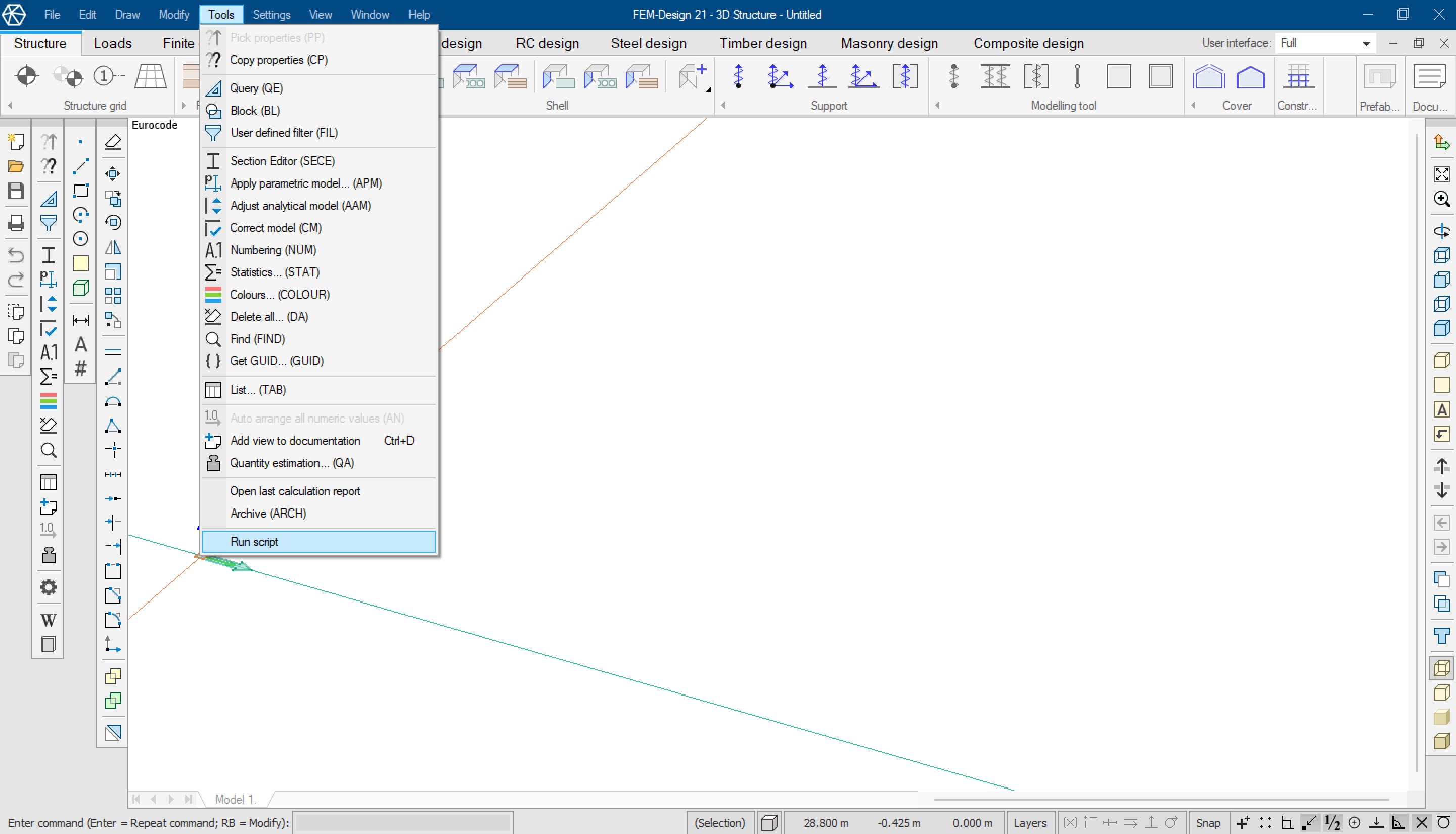
To launch the script use the menu command Tools -> Run script

or start the program with the command line:
C:\Program Files\StruSoft\FEM-Design 18\fd3dstruct.exe /s C:\Users\xxx\Desktop\MyDir\ExampleScript.fdscript
or, if you have fd3dstruct in your PATH, simply:
fd3dstruct /s c:\mydir\example.fdscript